HP 6715b HP Compaq 6715b and 6715s Notebook PC HP Compaq 6710b and 6710s Noteb - Page 101
PC Card/audio board assembly see
 |
UPC - 883585514274
View all HP 6715b manuals
Add to My Manuals
Save this manual to your list of manuals |
Page 101 highlights
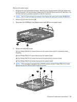
c. Optical drive (see Optical drive on page 62) d. Keyboard (see Keyboard on page 64) e. Switch cover (see Switch cover on page 70) f. Fan (see Fan on page 71) g. Heat sink (see Heat sink on page 72) h. Display assembly (see Display assembly on page 76) i. Top cover (see Top cover on page 81) j. System board (see System board on page 88) k. PC Card/audio board assembly (see PC Card/audio board assembly on page 91) Remove the modem module: 1. Turn the PC Card/audio board assembly upside down. 2. Remove the two Phillips PM2.5×3.0 screws (1) that secure the modem module to the PC Card/ audio board assembly. 3. Lift the modem module (2) straight up and remove it. Reverse this procedure to install the modem module. Component replacement procedures 93
-
 1
1 -
2
-
3
-
4
-
5
-
6
-
7
-
8
-
9
-
10
-
11
-
12
-
13
-
14
-
15
-
16
-
17
-
18
-
19
-
20
-
21
-
22
-
23
-
24
-
25
-
26
-
27
-
28
-
29
-
30
-
31
-
32
-
33
-
34
-
35
-
36
-
37
-
38
-
39
-
40
-
41
-
42
-
43
-
44
-
45
-
46
-
47
-
48
-
49
-
50
-
51
-
52
-
53
-
54
-
55
-
56
-
57
-
58
-
59
-
60
-
61
-
62
-
63
-
64
-
65
-
66
-
67
-
68
-
69
-
70
-
71
-
72
-
73
-
74
-
75
-
76
-
77
-
78
-
79
-
80
-
81
-
82
-
83
-
84
-
85
-
86
-
87
-
88
-
89
-
90
-
91
-
92
-
93
-
94
-
95
-
 96
96 -
 97
97 -
 98
98 -
 99
99 -
 100
100 -
 101
101 -
 102
102 -
 103
103 -
 104
104 -
 105
105 -
 106
106 -
107
-
108
-
109
-
110
-
111
-
112
-
113
-
114
-
115
-
116
-
117
-
118
-
119
-
120
-
121
-
122
-
123
-
124
-
125
-
126
-
127
-
128
-
129
-
130
-
131
-
132
-
133
-
134
-
135
-
136
-
137
-
138
-
139
-
140
-
141
-
142
-
143
-
144
-
145
-
146
-
147
-
148
-
149
-
150
-
151
-
152
-
153
-
154
-
155
-
156
-
157
-
158
-
159
-
160
-
161
-
162
-
163
-
164
-
165
-
166
-
167
-
168
-
169
-
170
 |
 |