HP 8510p HP Compaq 8510p Notebook PC and HP Compaq 8510w Mobile Workstation - - Page 100
Lift the left side of the USB/audio board, that secure the USB/audio board to the base
 |
UPC - 883585842872
View all HP 8510p manuals
Add to My Manuals
Save this manual to your list of manuals |
Page 100 highlights
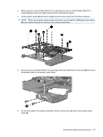
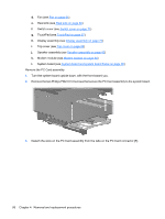
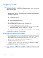
i. Top cover (see Top cover on page 80) j. Speaker assembly (see Speaker assembly on page 82) k. Modem module (see Modem module on page 84) l. System board (see System board and system board frame on page 85) Remove the USB/audio board: 1. Remove the two Phillips PM2.5×4.0 screws (1) that secure the USB/audio board to the base enclosure. 2. Lift the left side of the USB/audio board (2) until the USB and audio connectors disengage from the openings in the base enclosure. 3. Remove the USB/audio board and cables from the base enclosure. Reverse this procedure to install the USB/audio board. 92 Chapter 4 Removal and replacement procedures
-
 1
1 -
2
-
3
-
4
-
5
-
6
-
7
-
8
-
9
-
10
-
11
-
12
-
13
-
14
-
15
-
16
-
17
-
18
-
19
-
20
-
21
-
22
-
23
-
24
-
25
-
26
-
27
-
28
-
29
-
30
-
31
-
32
-
33
-
34
-
35
-
36
-
37
-
38
-
39
-
40
-
41
-
42
-
43
-
44
-
45
-
46
-
47
-
48
-
49
-
50
-
51
-
52
-
53
-
54
-
55
-
56
-
57
-
58
-
59
-
60
-
61
-
62
-
63
-
64
-
65
-
66
-
67
-
68
-
69
-
70
-
71
-
72
-
73
-
74
-
75
-
76
-
77
-
78
-
79
-
80
-
81
-
82
-
83
-
84
-
85
-
86
-
87
-
88
-
89
-
90
-
91
-
92
-
93
-
94
-
 95
95 -
 96
96 -
 97
97 -
 98
98 -
 99
99 -
 100
100 -
 101
101 -
 102
102 -
 103
103 -
 104
104 -
 105
105 -
106
-
107
-
108
-
109
-
110
-
111
-
112
-
113
-
114
-
115
-
116
-
117
-
118
-
119
-
120
-
121
-
122
-
123
-
124
-
125
-
126
-
127
-
128
-
129
-
130
-
131
-
132
-
133
-
134
-
135
-
136
-
137
-
138
-
139
-
140
-
141
-
142
-
143
-
144
-
145
-
146
-
147
-
148
-
149
-
150
-
151
-
152
-
153
-
154
-
155
-
156
-
157
-
158
-
159
-
160
-
161
-
162
-
163
-
164
-
165
-
166
-
167
-
168
-
169
-
170
 |
 |
i.
Top cover (see
Top cover
on page
80
)
j.
Speaker assembly (see
Speaker assembly
on page
82
)
k.
Modem module (see
Modem module
on page
84
)
l.
System board (see
System board and system board frame
on page
85
)
Remove the USB/audio board:
1.
Remove the two Phillips PM2.5×4.0 screws
(1)
that secure the USB/audio board to the base
enclosure.
2.
Lift the left side of the USB/audio board
(2)
until the USB and audio connectors disengage from
the openings in the base enclosure.
3.
Remove the USB/audio board and cables from the base enclosure.
Reverse this procedure to install the USB/audio board.
92
Chapter 4
Removal and replacement procedures