HP 8510p HP Compaq 8510p Notebook PC and HP Compaq 8510w Mobile Workstation - - Page 55
Display inverter, Remove the two Torx T8M2.5×7.0 screws
 |
UPC - 883585842872
View all HP 8510p manuals
Add to My Manuals
Save this manual to your list of manuals |
Page 55 highlights
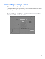
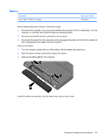
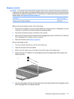
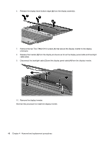
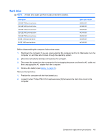
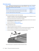
Display inverter NOTE: If it has been determined that the display inverter is the component that must be replaced to complete the computer repair, the display assembly does not have to be removed. Follow the procedures in this section to replace the display inverter. For information on replacing the display assembly and the display hinges, see Display assembly on page 75. Description Display inverter (includes 2-sided tape) Spare part number 452214-001 Before removing the display inverter, follow these steps: 1. Shut down the computer. If you are unsure whether the computer is off or in Hibernation, turn the computer on, and then shut it down through the operating system. 2. Disconnect all external devices connected to the computer. 3. Disconnect the power from the computer by first unplugging the power cord from the AC outlet and then unplugging the AC adapter from the computer. 4. Remove the battery (see Battery on page 45). Remove the display inverter: 1. Turn the computer right-side up, with the front toward you. 2. Open the computer as far as possible. 3. Remove the two rubber screw covers (1) on the bottom edge of the display bezel. 4. Remove the two Torx T8M2.5×7.0 screws (2) that secure the display bezel bottom edge to the display assembly. 5. Flex the inside edges of the left and right sides (1) and the display bezel bottom edge (2) until the bezel disengages from the display assembly. Component replacement procedures 47
-
 1
1 -
2
-
3
-
4
-
5
-
6
-
7
-
8
-
9
-
10
-
11
-
12
-
13
-
14
-
15
-
16
-
17
-
18
-
19
-
20
-
21
-
22
-
23
-
24
-
25
-
26
-
27
-
28
-
29
-
30
-
31
-
32
-
33
-
34
-
35
-
36
-
37
-
38
-
39
-
40
-
41
-
42
-
43
-
44
-
45
-
46
-
47
-
48
-
49
-
 50
50 -
 51
51 -
 52
52 -
 53
53 -
 54
54 -
 55
55 -
 56
56 -
 57
57 -
 58
58 -
 59
59 -
 60
60 -
61
-
62
-
63
-
64
-
65
-
66
-
67
-
68
-
69
-
70
-
71
-
72
-
73
-
74
-
75
-
76
-
77
-
78
-
79
-
80
-
81
-
82
-
83
-
84
-
85
-
86
-
87
-
88
-
89
-
90
-
91
-
92
-
93
-
94
-
95
-
96
-
97
-
98
-
99
-
100
-
101
-
102
-
103
-
104
-
105
-
106
-
107
-
108
-
109
-
110
-
111
-
112
-
113
-
114
-
115
-
116
-
117
-
118
-
119
-
120
-
121
-
122
-
123
-
124
-
125
-
126
-
127
-
128
-
129
-
130
-
131
-
132
-
133
-
134
-
135
-
136
-
137
-
138
-
139
-
140
-
141
-
142
-
143
-
144
-
145
-
146
-
147
-
148
-
149
-
150
-
151
-
152
-
153
-
154
-
155
-
156
-
157
-
158
-
159
-
160
-
161
-
162
-
163
-
164
-
165
-
166
-
167
-
168
-
169
-
170
 |
 |