HP 8510p HP Compaq 8510p Notebook PC and HP Compaq 8510w Mobile Workstation - - Page 98
Remove the PC Card assembly, Speaker assembly see
 |
UPC - 883585842872
View all HP 8510p manuals
Add to My Manuals
Save this manual to your list of manuals |
Page 98 highlights
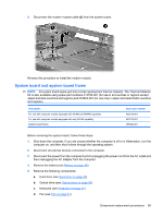
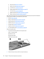
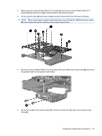
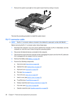
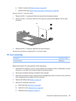
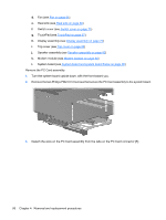
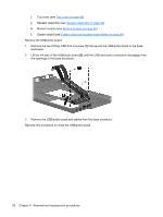
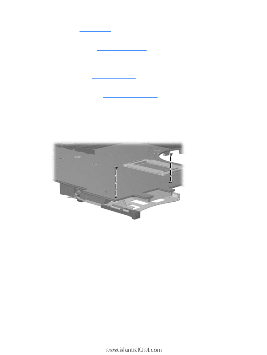
d. Fan (see Fan on page 61) e. Heat sink (see Heat sink on page 62) f. Switch cover (see Switch cover on page 71) g. TouchPad (see TouchPad on page 67) h. Display assembly (see Display assembly on page 75) i. Top cover (see Top cover on page 80) j. Speaker assembly (see Speaker assembly on page 82) k. Modem module (see Modem module on page 84) l. System board (see System board and system board frame on page 85) Remove the PC Card assembly: 1. Turn the system board upside down, with the front toward you. 2. Remove the two Phillips PM2.0×3.0 screws that secure the PC Card assembly to the system board. 3. Detach the slots on the PC Card assembly from the tabs on the PC Card connector (1). 90 Chapter 4 Removal and replacement procedures
-
 1
1 -
2
-
3
-
4
-
5
-
6
-
7
-
8
-
9
-
10
-
11
-
12
-
13
-
14
-
15
-
16
-
17
-
18
-
19
-
20
-
21
-
22
-
23
-
24
-
25
-
26
-
27
-
28
-
29
-
30
-
31
-
32
-
33
-
34
-
35
-
36
-
37
-
38
-
39
-
40
-
41
-
42
-
43
-
44
-
45
-
46
-
47
-
48
-
49
-
50
-
51
-
52
-
53
-
54
-
55
-
56
-
57
-
58
-
59
-
60
-
61
-
62
-
63
-
64
-
65
-
66
-
67
-
68
-
69
-
70
-
71
-
72
-
73
-
74
-
75
-
76
-
77
-
78
-
79
-
80
-
81
-
82
-
83
-
84
-
85
-
86
-
87
-
88
-
89
-
90
-
91
-
92
-
 93
93 -
 94
94 -
 95
95 -
 96
96 -
 97
97 -
 98
98 -
 99
99 -
 100
100 -
 101
101 -
 102
102 -
 103
103 -
104
-
105
-
106
-
107
-
108
-
109
-
110
-
111
-
112
-
113
-
114
-
115
-
116
-
117
-
118
-
119
-
120
-
121
-
122
-
123
-
124
-
125
-
126
-
127
-
128
-
129
-
130
-
131
-
132
-
133
-
134
-
135
-
136
-
137
-
138
-
139
-
140
-
141
-
142
-
143
-
144
-
145
-
146
-
147
-
148
-
149
-
150
-
151
-
152
-
153
-
154
-
155
-
156
-
157
-
158
-
159
-
160
-
161
-
162
-
163
-
164
-
165
-
166
-
167
-
168
-
169
-
170
 |
 |
d.
Fan (see
Fan
on page
61
)
e.
Heat sink (see
Heat sink
on page
62
)
f.
Switch cover (see
Switch cover
on page
71
)
g.
TouchPad (see
TouchPad
on page
67
)
h.
Display assembly (see
Display assembly
on page
75
)
i.
Top cover (see
Top cover
on page
80
)
j.
Speaker assembly (see
Speaker assembly
on page
82
)
k.
Modem module (see
Modem module
on page
84
)
l.
System board (see
System board and system board frame
on page
85
)
Remove the PC Card assembly:
1.
Turn the system board upside down, with the front toward you.
2.
Remove the two Phillips PM2.0×3.0 screws that secure the PC Card assembly to the system board.
3.
Detach the slots on the PC Card assembly from the tabs on the PC Card connector
(1)
.
90
Chapter 4
Removal and replacement procedures