HP 8510p HP Compaq 8510p Notebook PC and HP Compaq 8510w Mobile Workstation - - Page 95
that secure, and the two HM5.0×9.0 screw locks
 |
UPC - 883585842872
View all HP 8510p manuals
Add to My Manuals
Save this manual to your list of manuals |
Page 95 highlights
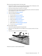
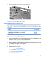
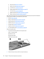
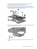
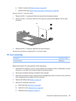
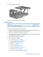
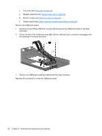
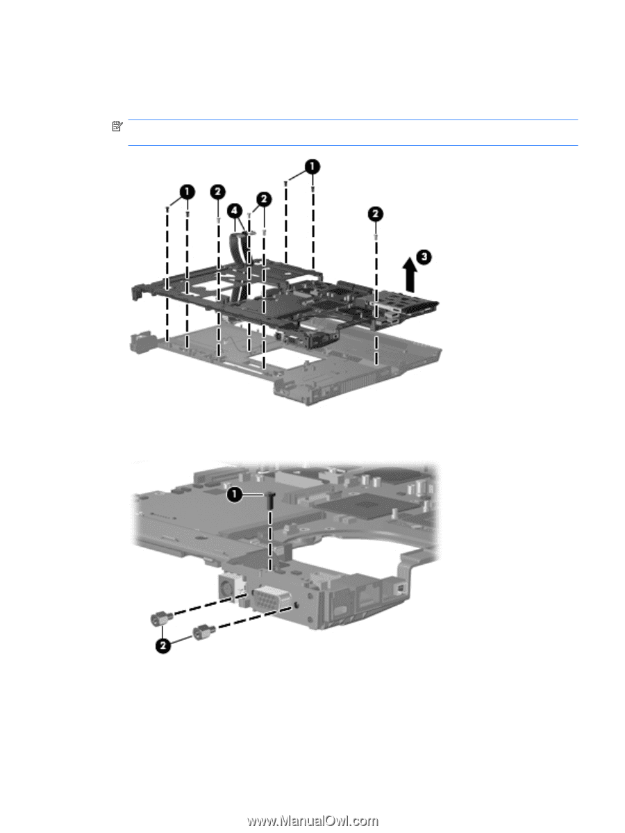
3. Remove the four black Phillips PM2.5×7.0 screws (1) and the four silver Phillips PM2.5×7.0 screws (2) that secure the system board frame to the base enclosure. 4. Lift the system board (3) and frame straight up and remove them from the base enclosure. NOTE: When removing the system board and frame, be sure that the USB/audio board cables (4) route cleanly through the opening in the system board frame. 5. Remove the silver Phillips PM2.5×7.0 screw (1) and the two HM5.0×9.0 screw locks (2) that secure the system board to the system board frame. 6. Lift the front edge of the system board (1) until the it clears the right side of the system board frame (2). Component replacement procedures 87
-
 1
1 -
2
-
3
-
4
-
5
-
6
-
7
-
8
-
9
-
10
-
11
-
12
-
13
-
14
-
15
-
16
-
17
-
18
-
19
-
20
-
21
-
22
-
23
-
24
-
25
-
26
-
27
-
28
-
29
-
30
-
31
-
32
-
33
-
34
-
35
-
36
-
37
-
38
-
39
-
40
-
41
-
42
-
43
-
44
-
45
-
46
-
47
-
48
-
49
-
50
-
51
-
52
-
53
-
54
-
55
-
56
-
57
-
58
-
59
-
60
-
61
-
62
-
63
-
64
-
65
-
66
-
67
-
68
-
69
-
70
-
71
-
72
-
73
-
74
-
75
-
76
-
77
-
78
-
79
-
80
-
81
-
82
-
83
-
84
-
85
-
86
-
87
-
88
-
89
-
 90
90 -
 91
91 -
 92
92 -
 93
93 -
 94
94 -
 95
95 -
 96
96 -
 97
97 -
 98
98 -
 99
99 -
 100
100 -
101
-
102
-
103
-
104
-
105
-
106
-
107
-
108
-
109
-
110
-
111
-
112
-
113
-
114
-
115
-
116
-
117
-
118
-
119
-
120
-
121
-
122
-
123
-
124
-
125
-
126
-
127
-
128
-
129
-
130
-
131
-
132
-
133
-
134
-
135
-
136
-
137
-
138
-
139
-
140
-
141
-
142
-
143
-
144
-
145
-
146
-
147
-
148
-
149
-
150
-
151
-
152
-
153
-
154
-
155
-
156
-
157
-
158
-
159
-
160
-
161
-
162
-
163
-
164
-
165
-
166
-
167
-
168
-
169
-
170
 |
 |
3.
Remove the four black Phillips PM2.5×7.0 screws
(1)
and the four silver Phillips PM2.5×7.0
screws
(2)
that secure the system board frame to the base enclosure.
4.
Lift the system board
(3)
and frame straight up and remove them from the base enclosure.
NOTE:
When removing the system board and frame, be sure that the USB/audio board cables
(4)
route cleanly through the opening in the system board frame.
5.
Remove the silver Phillips PM2.5×7.0 screw
(1)
and the two HM5.0×9.0 screw locks
(2)
that secure
the system board to the system board frame.
6.
Lift the front edge of the system board
(1)
until the it clears the right side of the system board
frame
(2)
.
Component replacement procedures
87