HP 8510p HP Compaq 8510p Notebook PC and HP Compaq 8510w Mobile Workstation - - Page 89
Remove the ten Torx T8M2.5×9.0 screws
 |
UPC - 883585842872
View all HP 8510p manuals
Add to My Manuals
Save this manual to your list of manuals |
Page 89 highlights
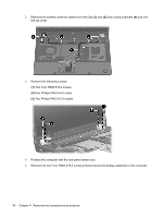
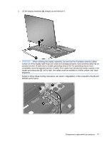
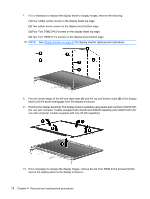
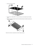
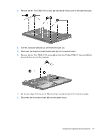
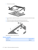
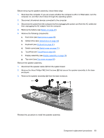
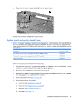
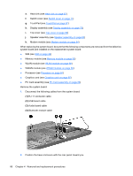
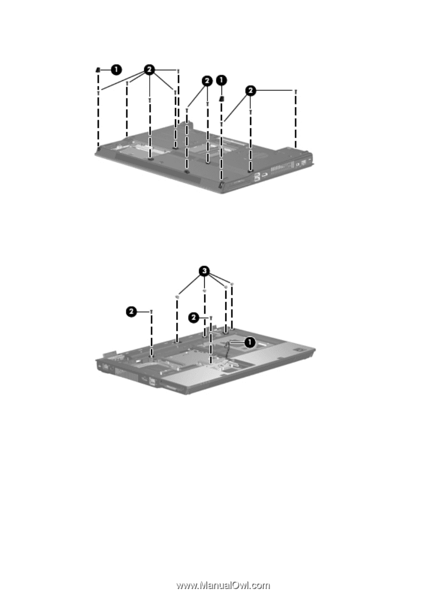
3. Remove the ten Torx T8M2.5×9.0 screws (2) that secure the top cover to the base enclosure. 4. Turn the computer right-side up, with the front toward you. 5. Disconnect the fingerprint reader board cable (1) from the system board. 6. Remove the two Torx T8M2.5×7.0 screws (2) and the four Phillips PM2.5×3.0 screws (3) that secure the top cover to the computer. 7. Lift the rear edge of the top cover (1) and swing it up and forward until it rests at an angle. 8. Disconnect the microphone cable (2) from the system board. Component replacement procedures 81
-
 1
1 -
2
-
3
-
4
-
5
-
6
-
7
-
8
-
9
-
10
-
11
-
12
-
13
-
14
-
15
-
16
-
17
-
18
-
19
-
20
-
21
-
22
-
23
-
24
-
25
-
26
-
27
-
28
-
29
-
30
-
31
-
32
-
33
-
34
-
35
-
36
-
37
-
38
-
39
-
40
-
41
-
42
-
43
-
44
-
45
-
46
-
47
-
48
-
49
-
50
-
51
-
52
-
53
-
54
-
55
-
56
-
57
-
58
-
59
-
60
-
61
-
62
-
63
-
64
-
65
-
66
-
67
-
68
-
69
-
70
-
71
-
72
-
73
-
74
-
75
-
76
-
77
-
78
-
79
-
80
-
81
-
82
-
83
-
 84
84 -
 85
85 -
 86
86 -
 87
87 -
 88
88 -
 89
89 -
 90
90 -
 91
91 -
 92
92 -
 93
93 -
 94
94 -
95
-
96
-
97
-
98
-
99
-
100
-
101
-
102
-
103
-
104
-
105
-
106
-
107
-
108
-
109
-
110
-
111
-
112
-
113
-
114
-
115
-
116
-
117
-
118
-
119
-
120
-
121
-
122
-
123
-
124
-
125
-
126
-
127
-
128
-
129
-
130
-
131
-
132
-
133
-
134
-
135
-
136
-
137
-
138
-
139
-
140
-
141
-
142
-
143
-
144
-
145
-
146
-
147
-
148
-
149
-
150
-
151
-
152
-
153
-
154
-
155
-
156
-
157
-
158
-
159
-
160
-
161
-
162
-
163
-
164
-
165
-
166
-
167
-
168
-
169
-
170
 |
 |
3.
Remove the ten Torx T8M2.5×9.0 screws
(2)
that secure the top cover to the base enclosure.
4.
Turn the computer right-side up, with the front toward you.
5.
Disconnect the fingerprint reader board cable
(1)
from the system board.
6.
Remove the two Torx T8M2.5×7.0 screws
(2)
and the four Phillips PM2.5×3.0 screws
(3)
that
secure the top cover to the computer.
7.
Lift the rear edge of the top cover
(1)
and swing it up and forward until it rests at an angle.
8.
Disconnect the microphone cable
(2)
from the system board.
Component replacement procedures
81