HP 8510p HP Compaq 8510p Notebook PC and HP Compaq 8510w Mobile Workstation - - Page 86
The display bezel is available using spare part numbers 455078-001
 |
UPC - 883585842872
View all HP 8510p manuals
Add to My Manuals
Save this manual to your list of manuals |
Page 86 highlights
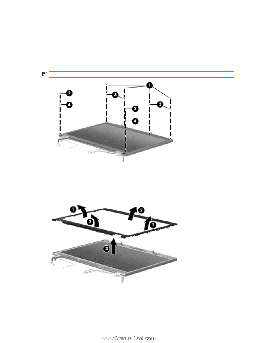
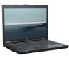
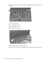
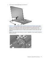
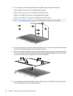
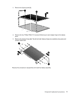
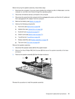
7. If it is necessary to replace the display bezel or display hinges, remove the following: (1) Four rubber screw covers on the display bezel top edge (2) Two rubber screw covers on the display bezel bottom edge (3) Four Torx T8M2.5×6.0 screws on the display bezel top edge (4) Two Torx T8M2.5×7.0 screws on the display bezel bottom edge NOTE: See Display inverter on page 47 for display inverter replacement instructions. 8. Flex the inside edges of the left and right sides (1) and the top and bottom sides (2) of the display bezel until the bezel disengages from the display enclosure. 9. Remove the display bezel (3). The display bezel is available using spare part numbers 455078-001 (for use with computer models equipped with WLAN and WWAN capability) and 452215-001 (for use with computer models equipped with only WLAN capability). 10. If it is necessary to replace the display hinges, remove the six Torx T8M2.5×6.0 screws (1) that secure the display panel to the display enclosure. 78 Chapter 4 Removal and replacement procedures
-
 1
1 -
2
-
3
-
4
-
5
-
6
-
7
-
8
-
9
-
10
-
11
-
12
-
13
-
14
-
15
-
16
-
17
-
18
-
19
-
20
-
21
-
22
-
23
-
24
-
25
-
26
-
27
-
28
-
29
-
30
-
31
-
32
-
33
-
34
-
35
-
36
-
37
-
38
-
39
-
40
-
41
-
42
-
43
-
44
-
45
-
46
-
47
-
48
-
49
-
50
-
51
-
52
-
53
-
54
-
55
-
56
-
57
-
58
-
59
-
60
-
61
-
62
-
63
-
64
-
65
-
66
-
67
-
68
-
69
-
70
-
71
-
72
-
73
-
74
-
75
-
76
-
77
-
78
-
79
-
80
-
 81
81 -
 82
82 -
 83
83 -
 84
84 -
 85
85 -
 86
86 -
 87
87 -
 88
88 -
 89
89 -
 90
90 -
 91
91 -
92
-
93
-
94
-
95
-
96
-
97
-
98
-
99
-
100
-
101
-
102
-
103
-
104
-
105
-
106
-
107
-
108
-
109
-
110
-
111
-
112
-
113
-
114
-
115
-
116
-
117
-
118
-
119
-
120
-
121
-
122
-
123
-
124
-
125
-
126
-
127
-
128
-
129
-
130
-
131
-
132
-
133
-
134
-
135
-
136
-
137
-
138
-
139
-
140
-
141
-
142
-
143
-
144
-
145
-
146
-
147
-
148
-
149
-
150
-
151
-
152
-
153
-
154
-
155
-
156
-
157
-
158
-
159
-
160
-
161
-
162
-
163
-
164
-
165
-
166
-
167
-
168
-
169
-
170
 |
 |