HP 8510p HP Compaq 8510p Notebook PC and HP Compaq 8510w Mobile Workstation - - Page 94
WWAN module see, Processor see
 |
UPC - 883585842872
View all HP 8510p manuals
Add to My Manuals
Save this manual to your list of manuals |
Page 94 highlights
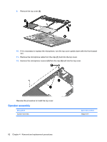
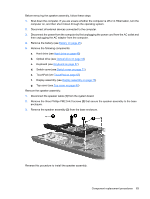
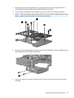
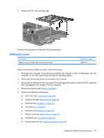
e. Heat sink (see Heat sink on page 62) f. Switch cover (see Switch cover on page 71) g. TouchPad (see TouchPad on page 67) h. Display assembly (see Display assembly on page 75) i. Top cover (see Top cover on page 80) j. Speaker assembly (see Speaker assembly on page 82) k. Modem module (see Modem module on page 84) When replacing the system board, be sure that the following components are removed from the defective system board and installed on the replacement system board: ● SIM (see SIM on page 46) ● Memory module (see Memory module on page 55) ● WLAN module (see WLAN module on page 69) ● WWAN module (see WWAN module on page 59) ● Processor (see Processor on page 64) ● Graphics card (see Graphics card on page 65) ● PC Card assembly (see PC Card assembly on page 89) Remove the system board: 1. Disconnect the following cables from the system board: (1) RJ-11 connector cable (2) USB board cable (3) Audio board cable (4) Bluetooth module cable 2. Position the base enclosure with the rear panel toward you. 86 Chapter 4 Removal and replacement procedures
-
 1
1 -
2
-
3
-
4
-
5
-
6
-
7
-
8
-
9
-
10
-
11
-
12
-
13
-
14
-
15
-
16
-
17
-
18
-
19
-
20
-
21
-
22
-
23
-
24
-
25
-
26
-
27
-
28
-
29
-
30
-
31
-
32
-
33
-
34
-
35
-
36
-
37
-
38
-
39
-
40
-
41
-
42
-
43
-
44
-
45
-
46
-
47
-
48
-
49
-
50
-
51
-
52
-
53
-
54
-
55
-
56
-
57
-
58
-
59
-
60
-
61
-
62
-
63
-
64
-
65
-
66
-
67
-
68
-
69
-
70
-
71
-
72
-
73
-
74
-
75
-
76
-
77
-
78
-
79
-
80
-
81
-
82
-
83
-
84
-
85
-
86
-
87
-
88
-
 89
89 -
 90
90 -
 91
91 -
 92
92 -
 93
93 -
 94
94 -
 95
95 -
 96
96 -
 97
97 -
 98
98 -
 99
99 -
100
-
101
-
102
-
103
-
104
-
105
-
106
-
107
-
108
-
109
-
110
-
111
-
112
-
113
-
114
-
115
-
116
-
117
-
118
-
119
-
120
-
121
-
122
-
123
-
124
-
125
-
126
-
127
-
128
-
129
-
130
-
131
-
132
-
133
-
134
-
135
-
136
-
137
-
138
-
139
-
140
-
141
-
142
-
143
-
144
-
145
-
146
-
147
-
148
-
149
-
150
-
151
-
152
-
153
-
154
-
155
-
156
-
157
-
158
-
159
-
160
-
161
-
162
-
163
-
164
-
165
-
166
-
167
-
168
-
169
-
170
 |
 |