HP 8510p HP Compaq 8510p Notebook PC and HP Compaq 8510w Mobile Workstation - - Page 74
edge of the board opposite the graphics card slot rises away from the computer.
 |
UPC - 883585842872
View all HP 8510p manuals
Add to My Manuals
Save this manual to your list of manuals |
Page 74 highlights
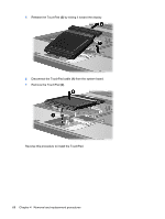
4. Remove the battery (see Battery on page 45). 5. Remove the following components: a. Keyboard (see Keyboard on page 57) b. Fan (see Fan on page 61) c. Heat sink (see Heat sink on page 62) Remove the graphics card: 1. Remove the two Phillips PM2.0×3.0 screws (1) that secure the graphics card to the computer. (The edge of the board opposite the graphics card slot rises away from the computer.) 2. Remove the graphics card (2) by sliding it away from the graphics card slot at an angle. NOTE: The graphics card is designed with a notch (3) to prevent incorrect installation. Reverse this procedure to install the graphics card. 66 Chapter 4 Removal and replacement procedures
-
 1
1 -
2
-
3
-
4
-
5
-
6
-
7
-
8
-
9
-
10
-
11
-
12
-
13
-
14
-
15
-
16
-
17
-
18
-
19
-
20
-
21
-
22
-
23
-
24
-
25
-
26
-
27
-
28
-
29
-
30
-
31
-
32
-
33
-
34
-
35
-
36
-
37
-
38
-
39
-
40
-
41
-
42
-
43
-
44
-
45
-
46
-
47
-
48
-
49
-
50
-
51
-
52
-
53
-
54
-
55
-
56
-
57
-
58
-
59
-
60
-
61
-
62
-
63
-
64
-
65
-
66
-
67
-
68
-
 69
69 -
 70
70 -
 71
71 -
 72
72 -
 73
73 -
 74
74 -
 75
75 -
 76
76 -
 77
77 -
 78
78 -
 79
79 -
80
-
81
-
82
-
83
-
84
-
85
-
86
-
87
-
88
-
89
-
90
-
91
-
92
-
93
-
94
-
95
-
96
-
97
-
98
-
99
-
100
-
101
-
102
-
103
-
104
-
105
-
106
-
107
-
108
-
109
-
110
-
111
-
112
-
113
-
114
-
115
-
116
-
117
-
118
-
119
-
120
-
121
-
122
-
123
-
124
-
125
-
126
-
127
-
128
-
129
-
130
-
131
-
132
-
133
-
134
-
135
-
136
-
137
-
138
-
139
-
140
-
141
-
142
-
143
-
144
-
145
-
146
-
147
-
148
-
149
-
150
-
151
-
152
-
153
-
154
-
155
-
156
-
157
-
158
-
159
-
160
-
161
-
162
-
163
-
164
-
165
-
166
-
167
-
168
-
169
-
170
 |
 |
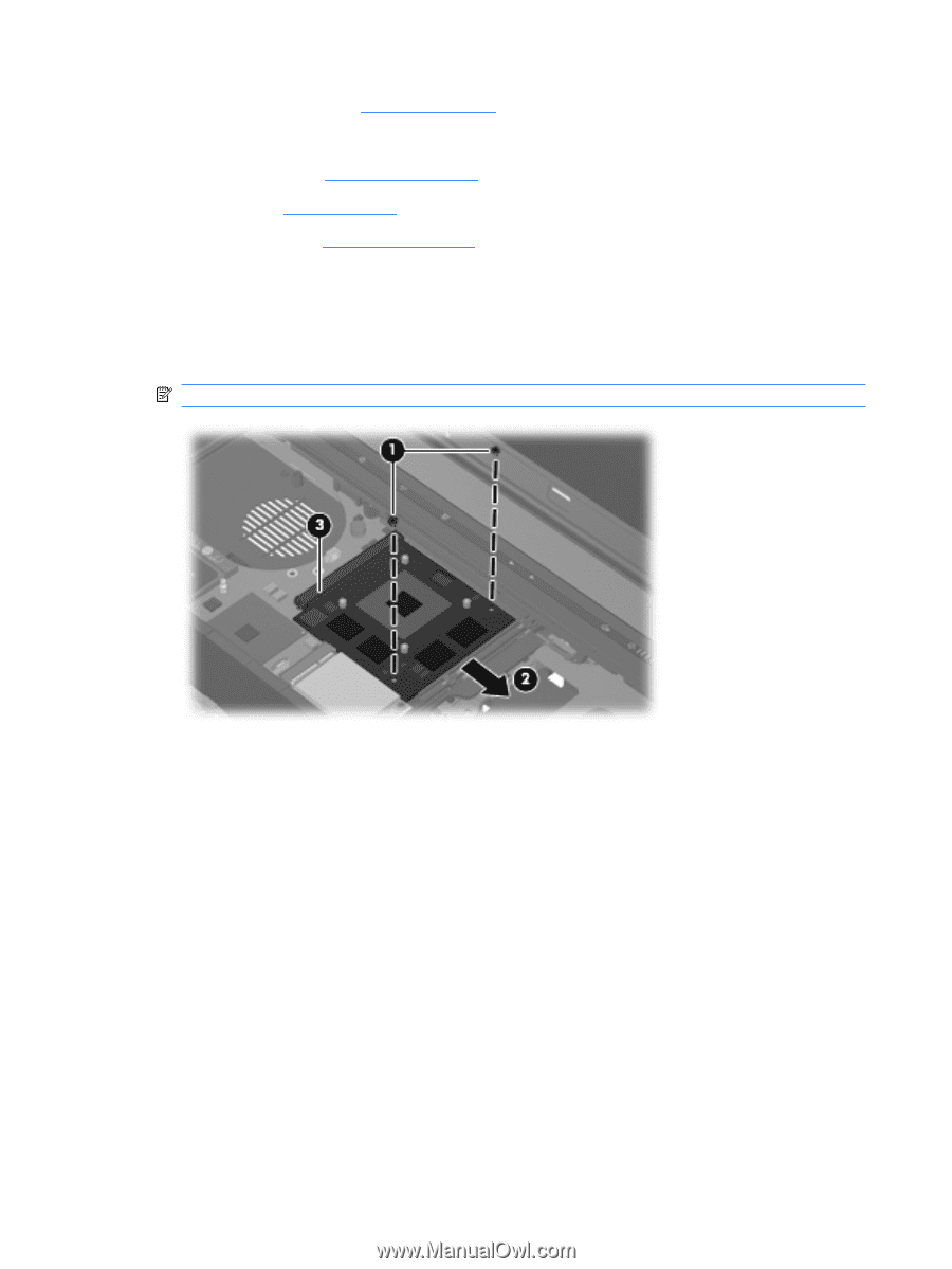
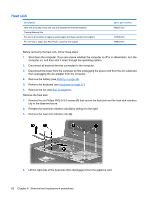
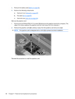
4.
Remove the battery (see
Battery
on page
45
).
5.
Remove the following components:
a.
Keyboard (see
Keyboard
on page
57
)
b.
Fan (see
Fan
on page
61
)
c.
Heat sink (see
Heat sink
on page
62
)
Remove the graphics card:
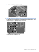
1.
Remove the two Phillips PM2.0×3.0 screws
(1)
that secure the graphics card to the computer. (The
edge of the board opposite the graphics card slot rises away from the computer.)
2.
Remove the graphics card
(2)
by sliding it away from the graphics card slot at an angle.
NOTE:
The graphics card is designed with a notch
(3)
to prevent incorrect installation.
Reverse this procedure to install the graphics card.
66
Chapter 4
Removal and replacement procedures