HP BladeSystem bc2500 Setup and Installation Guide HP BladeSystem bc2000 and b - Page 92
Blade PC and USB 1.1 Diagnostic Adapter LEDs, LEDs and Switches
 |
View all HP BladeSystem bc2500 manuals
Add to My Manuals
Save this manual to your list of manuals |
Page 92 highlights
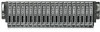
Table E-3 Hot-Plug Fan Health LEDs Item LED Status (1) Fan 1 Green = Normal (2) Fan 2 Amber = Failed (3) Fan 3 (4) Fan 4 Blade PC and USB 1.1 Diagnostic Adapter LEDs The blade PC and USB 1.1 diagnostic adapter LEDs have the same orientation and function. Use the following figures and table to determine the location and function of the LEDs. NOTE: The USB 2.0 diagnostic adapter has no LEDs. 84 Appendix E LEDs and Switches ENWW
-
 1
1 -
2
-
3
-
4
-
5
-
6
-
7
-
8
-
9
-
10
-
11
-
12
-
13
-
14
-
15
-
16
-
17
-
18
-
19
-
20
-
21
-
22
-
23
-
24
-
25
-
26
-
27
-
28
-
29
-
30
-
31
-
32
-
33
-
34
-
35
-
36
-
37
-
38
-
39
-
40
-
41
-
42
-
43
-
44
-
45
-
46
-
47
-
48
-
49
-
50
-
51
-
52
-
53
-
54
-
55
-
56
-
57
-
58
-
59
-
60
-
61
-
62
-
63
-
64
-
65
-
66
-
67
-
68
-
69
-
70
-
71
-
72
-
73
-
74
-
75
-
76
-
77
-
78
-
79
-
80
-
81
-
82
-
83
-
84
-
85
-
86
-
 87
87 -
 88
88 -
 89
89 -
 90
90 -
 91
91 -
 92
92 -
 93
93 -
 94
94 -
 95
95 -
 96
96 -
 97
97 -
98
-
99
-
100
-
101
-
102
-
103
-
104
 |
 |

Table E-3
Hot-Plug Fan Health LEDs
Item
LED
Status
(1)
(2)
(3)
(4)
Fan 1
Fan 2
Fan 3
Fan 4
Green = Normal
Amber = Failed
Blade PC and USB 1.1 Diagnostic Adapter LEDs
The blade PC and USB 1.1 diagnostic adapter LEDs have the same orientation and function. Use the
following figures and table to determine the location and function of the LEDs.
NOTE:
The USB 2.0 diagnostic adapter has no LEDs.
84
Appendix E
LEDs and Switches
ENWW