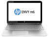
HP ENVY m6-n012dx HP ENVY m6 Notebook PC Maintenance and Service Guide - Page 38
Remove the Phillips PM2.0×2.5 screw
 |
View all HP ENVY m6-n012dx manuals
Add to My Manuals
Save this manual to your list of manuals |
Page 38 highlights
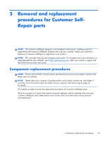
5. Remove the service cover (3). The service cover is available using spare part number 720555-001. 6. Disconnect the WLAN antenna cables (1) from the terminals on the WLAN module. NOTE: The WLAN antenna cable labeled "1" connects to the WLAN module "Main" terminal labeled "1". The WLAN antenna cable labeled "2" connects to the WLAN module "Aux" terminal labeled "2". 7. Remove the Phillips PM2.0×2.5 screw (2) that secures the WLAN module to the system board. (The WLAN module tilts up.) 30 Chapter 5 Removal and replacement procedures for Customer Self-Repair parts
-
 1
1 -
2
-
3
-
4
-
5
-
6
-
7
-
8
-
9
-
10
-
11
-
12
-
13
-
14
-
15
-
16
-
17
-
18
-
19
-
20
-
21
-
22
-
23
-
24
-
25
-
26
-
27
-
28
-
29
-
30
-
31
-
32
-
 33
33 -
 34
34 -
 35
35 -
 36
36 -
 37
37 -
 38
38 -
 39
39 -
 40
40 -
 41
41 -
 42
42 -
 43
43 -
44
-
45
-
46
-
47
-
48
-
49
-
50
-
51
-
52
-
53
-
54
-
55
-
56
-
57
-
58
-
59
-
60
-
61
-
62
-
63
-
64
-
65
-
66
-
67
-
68
-
69
-
70
-
71
-
72
-
73
-
74
-
75
-
76
-
77
-
78
-
79
-
80
-
81
-
82
-
83
-
84
-
85
-
86
-
87
-
88
 |
 |
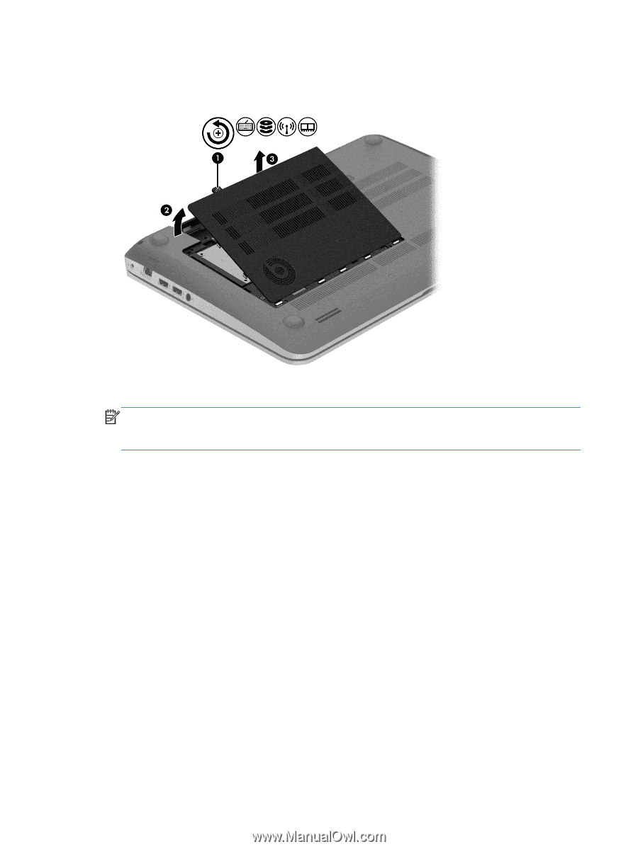
5.
Remove the service cover
(3)
.
The service cover is available using spare part number 720555-001.
6.
Disconnect the WLAN antenna cables
(1)
from the terminals on the WLAN module.
NOTE:
The WLAN antenna cable labeled “1” connects to the WLAN module “Main” terminal
labeled “1”. The WLAN antenna cable labeled “2” connects to the WLAN module “Aux” terminal
labeled “2”.
7.
Remove the Phillips PM2.0×2.5 screw
(2)
that secures the WLAN module to the system board.
(The WLAN module tilts up.)
30
Chapter 5
Removal and replacement procedures for Customer Self-Repair parts