HP ENVY m6-n012dx HP ENVY m6 Notebook PC Maintenance and Service Guide - Page 61
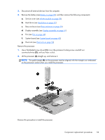
until you hear a click., to turn the processor locking screw one-half turn
 |
View all HP ENVY m6-n012dx manuals
Add to My Manuals
Save this manual to your list of manuals |
Page 61 highlights
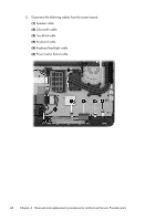
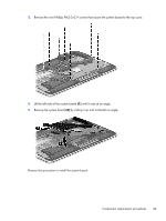
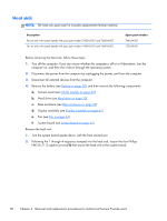
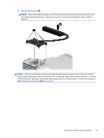
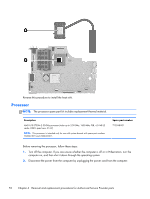
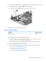
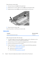
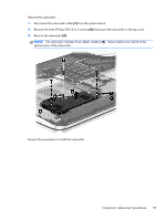
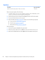
3. Disconnect all external devices from the computer. 4. Remove the battery (see Battery on page 28), and then remove the following components: a. Service cover (see WLAN module on page 29) b. Hard drive (see Hard drive on page 32) c. Base enclosure (see Base enclosure on page 39) d. Display assembly (see Display assembly on page 41) e. Fan (see Fan on page 44) f. System board (see System board on page 45) g. Heat sink (see Heat sink on page 50) Remove the processor: 1. Use a flat-bladed screw driver (1) to turn the processor locking screw one-half turn counterclockwise (2), until you hear a click. 2. Lift the processor (3) straight up, and remove it. NOTE: The gold triangle (4) on the processor must be aligned with the triangle icon embossed on the processor socket when you install the processor. Reverse this procedure to install the processor. Component replacement procedures 53
-
 1
1 -
2
-
3
-
4
-
5
-
6
-
7
-
8
-
9
-
10
-
11
-
12
-
13
-
14
-
15
-
16
-
17
-
18
-
19
-
20
-
21
-
22
-
23
-
24
-
25
-
26
-
27
-
28
-
29
-
30
-
31
-
32
-
33
-
34
-
35
-
36
-
37
-
38
-
39
-
40
-
41
-
42
-
43
-
44
-
45
-
46
-
47
-
48
-
49
-
50
-
51
-
52
-
53
-
54
-
55
-
 56
56 -
 57
57 -
 58
58 -
 59
59 -
 60
60 -
 61
61 -
 62
62 -
 63
63 -
 64
64 -
 65
65 -
 66
66 -
67
-
68
-
69
-
70
-
71
-
72
-
73
-
74
-
75
-
76
-
77
-
78
-
79
-
80
-
81
-
82
-
83
-
84
-
85
-
86
-
87
-
88
 |
 |
