HP ENVY m6-n012dx HP ENVY m6 Notebook PC Maintenance and Service Guide - Page 47
Base enclosure, Remove the front rubber feet
 |
View all HP ENVY m6-n012dx manuals
Add to My Manuals
Save this manual to your list of manuals |
Page 47 highlights
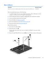
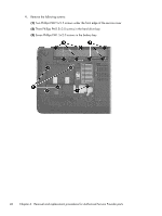
Base enclosure Description Base enclosure (includes 4 rubber feet, battery lock latch, battery release latch, and RJ-45 cover) Spare part number 760035-001 Before removing the base enclosure, follow these steps: 1. Turn off the computer. If you are unsure whether the computer is off or in Hibernation, turn the computer on, and then shut it down through the operating system. 2. Disconnect the power from the computer by unplugging the power cord from the computer. 3. Disconnect all external devices from the computer. 4. Remove the battery (see Battery on page 28). 5. Remove the solid-state drive (see WLAN module on page 29). 6. Remove the hard drive (see Hard drive on page 32). Remove the base enclosure: 1. Remove the front rubber feet (1). 2. Remove the screw cover (2). The front rubber feet and the screw cover are included in the Rubber Kit, spare part number 720559-001. 3. Remove the eight Phillips PM2.5×5.5 screws (2) that secure the base enclosure to the computer. Component replacement procedures 39
-
 1
1 -
2
-
3
-
4
-
5
-
6
-
7
-
8
-
9
-
10
-
11
-
12
-
13
-
14
-
15
-
16
-
17
-
18
-
19
-
20
-
21
-
22
-
23
-
24
-
25
-
26
-
27
-
28
-
29
-
30
-
31
-
32
-
33
-
34
-
35
-
36
-
37
-
38
-
39
-
40
-
41
-
 42
42 -
 43
43 -
 44
44 -
 45
45 -
 46
46 -
 47
47 -
 48
48 -
 49
49 -
 50
50 -
 51
51 -
 52
52 -
53
-
54
-
55
-
56
-
57
-
58
-
59
-
60
-
61
-
62
-
63
-
64
-
65
-
66
-
67
-
68
-
69
-
70
-
71
-
72
-
73
-
74
-
75
-
76
-
77
-
78
-
79
-
80
-
81
-
82
-
83
-
84
-
85
-
86
-
87
-
88
 |
 |