HP ENVY m6-n012dx HP ENVY m6 Notebook PC Maintenance and Service Guide - Page 63
Power connector cable
 |
View all HP ENVY m6-n012dx manuals
Add to My Manuals
Save this manual to your list of manuals |
Page 63 highlights
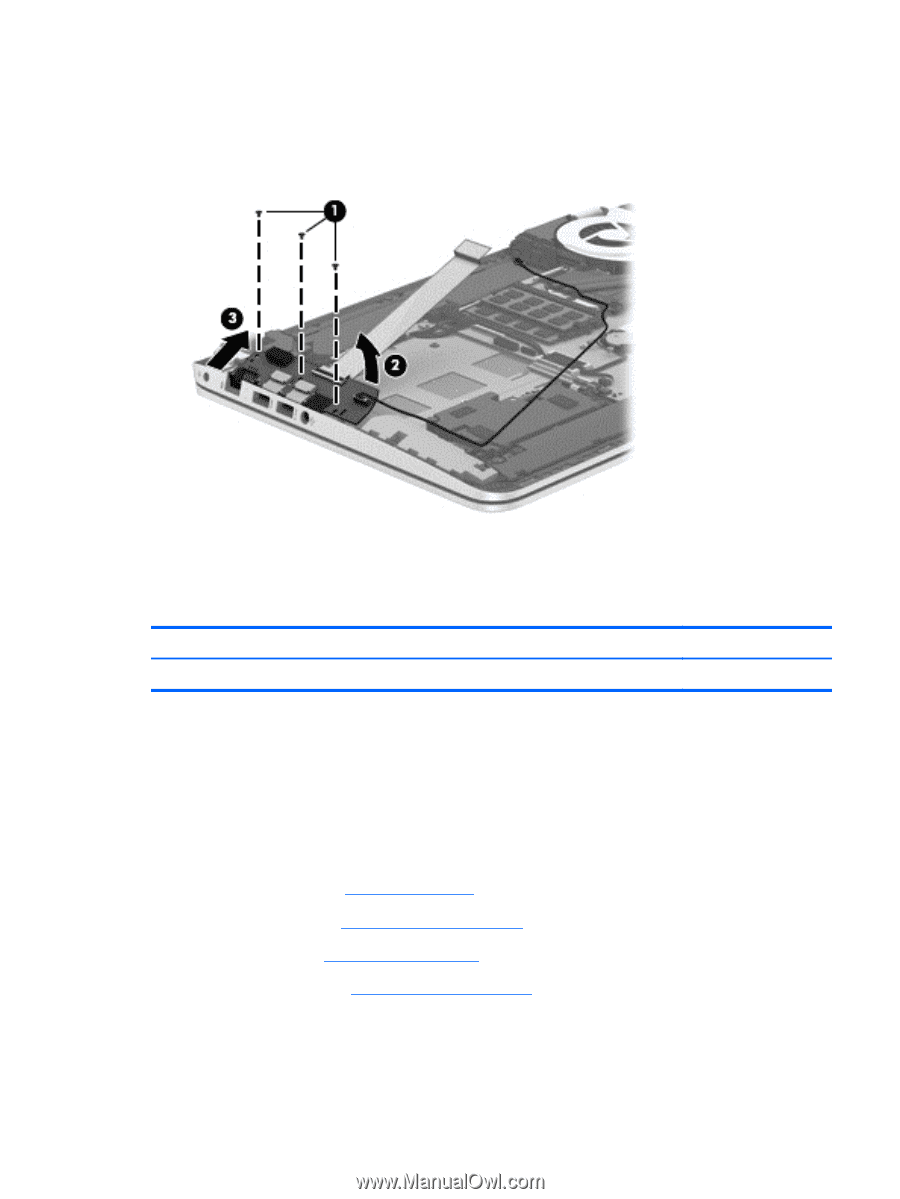
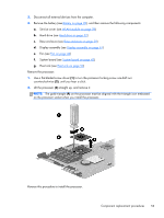
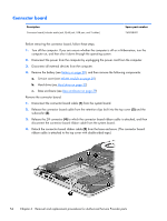
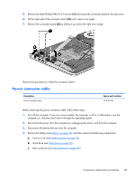
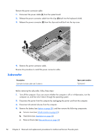
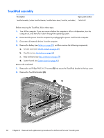
5. Remove the three Phillips PM2.0×2.9 screws (1) that secure the connector board to the top cover. 6. Lift the right side of the connector board (2) until it rests at an angle. 7. Remove the connector board (3) by sliding it up and to the right at an angle. Reverse this procedure to install the connector board. Power connector cable Description Power connector cable Spare part number 720537-001 Before removing the power connector cable, follow these steps: 1. Turn off the computer. If you are unsure whether the computer is off or in Hibernation, turn the computer on, and then shut it down through the operating system. 2. Disconnect the power from the computer by unplugging the power cord from the computer. 3. Disconnect all external devices from the computer. 4. Remove the battery (see Battery on page 28), and then remove the following components: a. Service cover (see WLAN module on page 29) b. Hard drive (see Hard drive on page 32) c. Base enclosure (see Base enclosure on page 39) Component replacement procedures 55
-
 1
1 -
2
-
3
-
4
-
5
-
6
-
7
-
8
-
9
-
10
-
11
-
12
-
13
-
14
-
15
-
16
-
17
-
18
-
19
-
20
-
21
-
22
-
23
-
24
-
25
-
26
-
27
-
28
-
29
-
30
-
31
-
32
-
33
-
34
-
35
-
36
-
37
-
38
-
39
-
40
-
41
-
42
-
43
-
44
-
45
-
46
-
47
-
48
-
49
-
50
-
51
-
52
-
53
-
54
-
55
-
56
-
57
-
 58
58 -
 59
59 -
 60
60 -
 61
61 -
 62
62 -
 63
63 -
 64
64 -
 65
65 -
 66
66 -
 67
67 -
 68
68 -
69
-
70
-
71
-
72
-
73
-
74
-
75
-
76
-
77
-
78
-
79
-
80
-
81
-
82
-
83
-
84
-
85
-
86
-
87
-
88
 |
 |