HP EliteBook G7 Maintenance and Service Guide - Page 68
System board, Table 6-12
 |
View all HP EliteBook G7 manuals
Add to My Manuals
Save this manual to your list of manuals |
Page 68 highlights
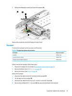
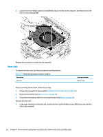
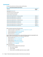
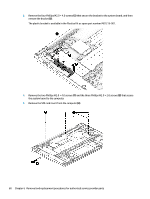
System board To remove the system board, use these procedures and illustrations. Table 6-12 System board descriptions and part numbers Description System board (includes processor): All system boards use the following part numbers: xxxxxx-001: Non-Windows operating system xxxxxx-601: Windows 10 operating system System board with integrated Intel Core i7-10810 processor (OSR) System board with integrated Intel Core i7-10710 processor System board with integrated Intel Core i7-10610 processor System board with integrated Intel Core i7-10610 processor (OSR) System board with integrated Intel Core i7-10510 processor System board with integrated Intel Core i5-10310 processor System board with integrated Intel Core i5-10310 processor (OSR) System board with integrated Intel Core i5-10210 processor Spare part number M08564-xx1 M08563-xx1 M08561-xx1 M08562-xx1 M08558-xx1 M08559-xx1 M08560-xx1 M08557-xx1 Before removing the system board, follow these steps: 1. Prepare the computer for disassembly (Preparation for disassembly on page 35). 2. Remove the bottom cover (Bottom cover on page 35). 3. Remove the battery (see Battery on page 45). 4. Remove the fan (see Fan on page 55). When you replace the system board, be sure to remove the following components (as applicable) from the defective system board and install them on the replacement system board: ● Memory modules (see Memory modules on page 36). ● WLAN module (see WLAN module on page 39). ● WWAN module (see WWAN module on page 40). ● Solid-state drive (see Solid-state drive on page 42). ● Heat sink (see Heat sink on page 56). Remove the system board: 1. Disconnect the following cables from the system board: ● Power connector cable (1) ● Camera cable (2) ● Antenna cables from the WWAN module (select products only) (3) 58 Chapter 6 Removal and replacement procedures for authorized service provider parts
-
 1
1 -
2
-
3
-
4
-
5
-
6
-
7
-
8
-
9
-
10
-
11
-
12
-
13
-
14
-
15
-
16
-
17
-
18
-
19
-
20
-
21
-
22
-
23
-
24
-
25
-
26
-
27
-
28
-
29
-
30
-
31
-
32
-
33
-
34
-
35
-
36
-
37
-
38
-
39
-
40
-
41
-
42
-
43
-
44
-
45
-
46
-
47
-
48
-
49
-
50
-
51
-
52
-
53
-
54
-
55
-
56
-
57
-
58
-
59
-
60
-
61
-
62
-
 63
63 -
 64
64 -
 65
65 -
 66
66 -
 67
67 -
 68
68 -
 69
69 -
 70
70 -
 71
71 -
 72
72 -
 73
73 -
74
-
75
-
76
-
77
-
78
-
79
-
80
-
81
-
82
-
83
-
84
-
85
-
86
-
87
-
88
-
89
-
90
-
91
-
92
-
93
-
94
-
95
-
96
-
97
-
98
-
99
-
100
-
101
-
102
-
103
-
104
-
105
-
106
-
107
-
108
-
109
-
110
-
111
-
112
-
113
-
114
 |
 |