HP EliteBook G7 Maintenance and Service Guide - Page 72
Phillips M2.5 × 4.0 screws, that secure the display assembly to the computer.
 |
View all HP EliteBook G7 manuals
Add to My Manuals
Save this manual to your list of manuals |
Page 72 highlights
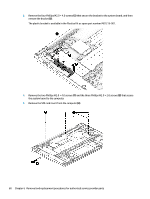
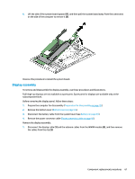
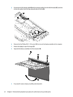
2. Disconnect the left display cable (4) and the antenna cables from the WLAN module (5), and then remove the cables from the clips along the side of the fan (6). 3. Remove the five Phillips M2.5 × 4.0 screws (1) that secure the display assembly to the computer. 4. Rotate the display to open the hinges (2). 5. Separate the display assembly from the computer (3). 6. If you need to replace display assembly subcomponents: 62 Chapter 6 Removal and replacement procedures for authorized service provider parts
-
 1
1 -
2
-
3
-
4
-
5
-
6
-
7
-
8
-
9
-
10
-
11
-
12
-
13
-
14
-
15
-
16
-
17
-
18
-
19
-
20
-
21
-
22
-
23
-
24
-
25
-
26
-
27
-
28
-
29
-
30
-
31
-
32
-
33
-
34
-
35
-
36
-
37
-
38
-
39
-
40
-
41
-
42
-
43
-
44
-
45
-
46
-
47
-
48
-
49
-
50
-
51
-
52
-
53
-
54
-
55
-
56
-
57
-
58
-
59
-
60
-
61
-
62
-
63
-
64
-
65
-
66
-
 67
67 -
 68
68 -
 69
69 -
 70
70 -
 71
71 -
 72
72 -
 73
73 -
 74
74 -
 75
75 -
 76
76 -
 77
77 -
78
-
79
-
80
-
81
-
82
-
83
-
84
-
85
-
86
-
87
-
88
-
89
-
90
-
91
-
92
-
93
-
94
-
95
-
96
-
97
-
98
-
99
-
100
-
101
-
102
-
103
-
104
-
105
-
106
-
107
-
108
-
109
-
110
-
111
-
112
-
113
-
114
 |
 |

2.
Disconnect the left display cable
(4)
and the antenna cables from the WLAN module
(5)
, and then
remove the cables from the clips along the side of the fan
(6)
.
3.
Remove the
five
Phillips M2.5 × 4.0 screws
(1)
that secure the display assembly to the computer.
4.
Rotate the display to open the hinges
(2)
.
5.
Separate the display assembly from the computer
(3)
.
6.
If you need to replace display assembly subcomponents:
62
Chapter 6
Removal and replacement procedures for authorized service provider parts