HP GbE2c HP BladeSystem c7000 Enclosure Maintenance and Service Guide - Page 39
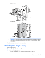
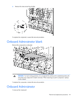
Disconnect the Insight Display cable.
 |
UPC - 808736802215
View all HP GbE2c manuals
Add to My Manuals
Save this manual to your list of manuals |
Page 39 highlights
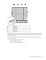
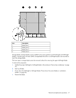
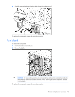
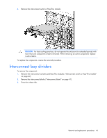
o Full-height blades: bays 1-5 ("Half-height or full-height blade" on page 36) o Device bay blanks: bays 9-13 ("Device bay blank" on page 33) o Power supplies or blanks: bays 1-4 ("HP BladeSystem c7000 power supply or power supply blank" on page 32) 3. Remove the three T-15 Torx screws that secure the Insight Display cable center cover, and then remove the cover. 4. Disconnect the Insight Display cable. 5. Remove the two T-10 Torx screws that secure the Insight Display. 6. Remove the upper brace. 7. Tilt the Insight Display forward and remove it from the enclosure. Removal and replacement procedures 39
-
 1
1 -
2
-
3
-
4
-
5
-
6
-
7
-
8
-
9
-
10
-
11
-
12
-
13
-
14
-
15
-
16
-
17
-
18
-
19
-
20
-
21
-
22
-
23
-
24
-
25
-
26
-
27
-
28
-
29
-
30
-
31
-
32
-
33
-
 34
34 -
 35
35 -
 36
36 -
 37
37 -
 38
38 -
 39
39 -
 40
40 -
 41
41 -
 42
42 -
 43
43 -
 44
44 -
45
-
46
-
47
-
48
-
49
-
50
-
51
-
52
-
53
-
54
-
55
-
56
-
57
-
58
-
59
-
60
-
61
-
62
-
63
-
64
-
65
-
66
-
67
-
68
-
69
-
70
-
71
-
72
-
73
-
74
-
75
-
76
-
77
 |
 |
Removal and replacement procedures
39
o
Full-height blades: bays 1-5 ("Half-height or full-height blade" on page 36)
o
Device bay blanks: bays 9-13 ("Device bay blank" on page 33)
o
Power supplies or blanks: bays 1-4 ("HP BladeSystem c7000 power supply or power supply
blank" on page 32)
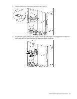
3.
Remove the three T-15 Torx screws that secure the Insight Display cable center cover, and then
remove the cover.
4.
Disconnect the Insight Display cable.
5.
Remove the two T-10 Torx screws that secure the Insight Display.
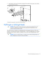
6.
Remove the upper brace.
7.
Tilt the Insight Display forward and remove it from the enclosure.