HP GbE2c HP BladeSystem c7000 Enclosure Maintenance and Service Guide - Page 51
Insight Display signal pass-thru board
 |
UPC - 808736802215
View all HP GbE2c manuals
Add to My Manuals
Save this manual to your list of manuals |
Page 51 highlights
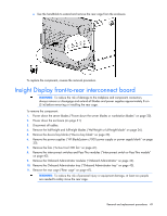
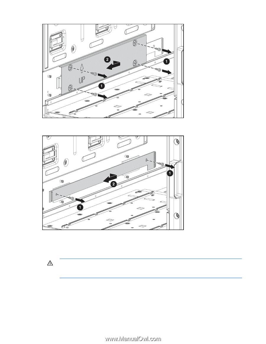
15. Remove the two slotted T-15 Torx screws that secure the interconnect board. 16. Remove the interconnect board. To replace the component, reverse the removal procedure. Insight Display signal pass-thru board WARNING: To reduce the risk of damage to the midplane and component connectors, always remove or disengage and extend all blades and power supplies approximately 8 cm (3 in) before removing or installing the rear cage. To remove the component: 1. Power down the server blades ("Power down the server blades or workstation blades" on page 30). 2. Power down the enclosure (on page 31). 3. Disconnect all cables. Removal and replacement procedures 51
-
 1
1 -
2
-
3
-
4
-
5
-
6
-
7
-
8
-
9
-
10
-
11
-
12
-
13
-
14
-
15
-
16
-
17
-
18
-
19
-
20
-
21
-
22
-
23
-
24
-
25
-
26
-
27
-
28
-
29
-
30
-
31
-
32
-
33
-
34
-
35
-
36
-
37
-
38
-
39
-
40
-
41
-
42
-
43
-
44
-
45
-
 46
46 -
 47
47 -
 48
48 -
 49
49 -
 50
50 -
 51
51 -
 52
52 -
 53
53 -
 54
54 -
 55
55 -
 56
56 -
57
-
58
-
59
-
60
-
61
-
62
-
63
-
64
-
65
-
66
-
67
-
68
-
69
-
70
-
71
-
72
-
73
-
74
-
75
-
76
-
77
 |
 |
Removal and replacement procedures
51
15.
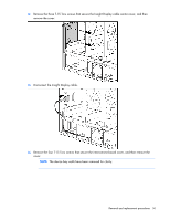
Remove the two slotted T-15 Torx screws that secure the interconnect board.
16.
Remove the interconnect board.
To replace the component, reverse the removal procedure.
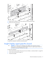
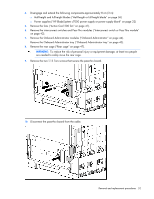
Insight Display signal pass-thru board
WARNING:
To reduce the risk of damage to the midplane and component connectors,
always remove or disengage and extend all blades and power supplies approximately 8 cm
(3 in) before removing or installing the rear cage.
To remove the component:
1.
Power down the server blades ("Power down the server blades or workstation blades" on page 30).
2.
Power down the enclosure (on page 31).
3.
Disconnect all cables.