HP GbE2c HP BladeSystem c7000 Enclosure Maintenance and Service Guide - Page 53
Midplane assembly - user guide
 |
UPC - 808736802215
View all HP GbE2c manuals
Add to My Manuals
Save this manual to your list of manuals |
Page 53 highlights
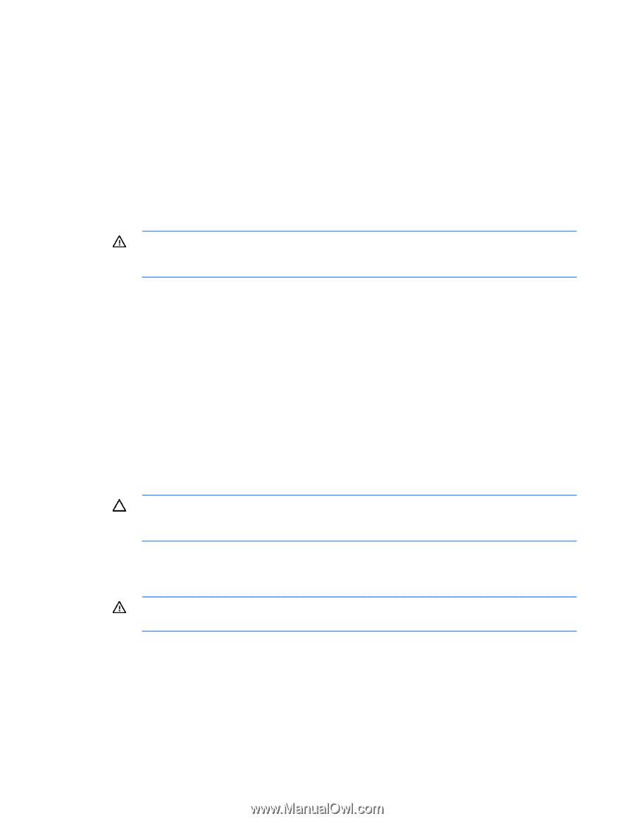
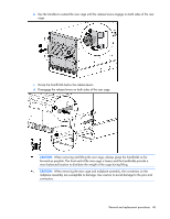
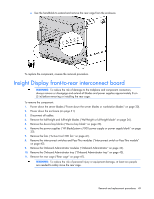
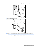
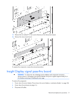
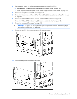
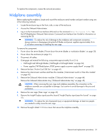
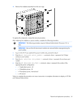
To replace the component, reverse the removal procedure. Midplane assembly Before replacing the midplane, locate and record the enclosure serial number and part number using one of the following methods: • Locate the enclosure tag on the front, side, or rear of the enclosure. • Access the Onboard Administrator. • Log in to the Command Line Interface (CLI) and run the command Show Enclosure Info. See the HP BladeSystem Onboard Administrator Command Line Interface User Guide for information on accessing the CLI. WARNING: To reduce the risk of damage to the midplane and component connectors, always remove or disengage and extend all blades and power supplies approximately 8 cm (3 in) before removing or installing the rear cage. To remove the component: 1. Power down the server blades ("Power down the server blades or workstation blades" on page 30). 2. Power down the enclosure (on page 31). 3. Disconnect all cables. 4. Disengage and extend the following components approximately 8 cm (3 in): o Half-height and full-height blades ("Half-height or full-height blade" on page 36) o Power supplies ("HP BladeSystem c7000 power supply or power supply blank" on page 32) 5. Remove the fans ("Active Cool 200 fan" on page 41). 6. Remove the interconnect switches and Pass-Thru modules ("Interconnect switch or Pass-Thru module" on page 42). 7. Remove the Onboard Administrator modules ("Onboard Administrator" on page 44). Remove the Onboard Administrator tray ("Onboard Administrator tray" on page 45). CAUTION: When removing the rear cage and midplane assembly, the connectors on the midplane assembly are susceptible to damage. Use caution to avoid damage to the pins and connectors. 8. Remove the rear cage ("Rear cage" on page 47). 9. Remove the Insight Display signal pass-thru board ("Insight Display signal pass-thru board" on page 51). WARNING: To reduce the risk of personal injury or equipment damage, at least two people are needed to safely move the rear cage. 10. Remove the eight slotted T-15 Torx screws that secure the midplane assembly. Removal and replacement procedures 53
-
 1
1 -
2
-
3
-
4
-
5
-
6
-
7
-
8
-
9
-
10
-
11
-
12
-
13
-
14
-
15
-
16
-
17
-
18
-
19
-
20
-
21
-
22
-
23
-
24
-
25
-
26
-
27
-
28
-
29
-
30
-
31
-
32
-
33
-
34
-
35
-
36
-
37
-
38
-
39
-
40
-
41
-
42
-
43
-
44
-
45
-
46
-
47
-
 48
48 -
 49
49 -
 50
50 -
 51
51 -
 52
52 -
 53
53 -
 54
54 -
 55
55 -
 56
56 -
 57
57 -
 58
58 -
59
-
60
-
61
-
62
-
63
-
64
-
65
-
66
-
67
-
68
-
69
-
70
-
71
-
72
-
73
-
74
-
75
-
76
-
77
 |
 |