HP LaserJet 6p/mp Service Manual - Page 83
Assembly fit under the sheet metal fuser plate below.
 |
View all HP LaserJet 6p/mp manuals
Add to My Manuals
Save this manual to your list of manuals |
Page 83 highlights
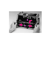
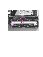
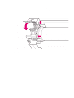
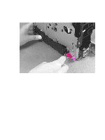
3 Use the magnetic screwdriver to remove the (2) screws (Figure 6-10, callout 1). 4 Rotate the rear of the Delivery Assembly up and forward, then lift it out of the printer. 1 Figure 6-10 Delivery Assembly removal (2 of 2) Note When reinstalling the Delivery Assembly, make sure that the tabs on the front end of the Delivery Assembly fit under the sheet metal fuser plate below. EN Internal assemblies 81
-
 1
1 -
2
-
3
-
4
-
5
-
6
-
7
-
8
-
9
-
10
-
11
-
12
-
13
-
14
-
15
-
16
-
17
-
18
-
19
-
20
-
21
-
22
-
23
-
24
-
25
-
26
-
27
-
28
-
29
-
30
-
31
-
32
-
33
-
34
-
35
-
36
-
37
-
38
-
39
-
40
-
41
-
42
-
43
-
44
-
45
-
46
-
47
-
48
-
49
-
50
-
51
-
52
-
53
-
54
-
55
-
56
-
57
-
58
-
59
-
60
-
61
-
62
-
63
-
64
-
65
-
66
-
67
-
68
-
69
-
70
-
71
-
72
-
73
-
74
-
75
-
76
-
77
-
 78
78 -
 79
79 -
 80
80 -
 81
81 -
 82
82 -
 83
83 -
 84
84 -
 85
85 -
 86
86 -
 87
87 -
 88
88 -
89
-
90
-
91
-
92
-
93
-
94
-
95
-
96
-
97
-
98
-
99
-
100
-
101
-
102
-
103
-
104
-
105
-
106
-
107
-
108
-
109
-
110
-
111
-
112
-
113
-
114
-
115
-
116
-
117
-
118
-
119
-
120
-
121
-
122
-
123
-
124
-
125
-
126
-
127
-
128
-
129
-
130
-
131
-
132
-
133
-
134
-
135
-
136
-
137
-
138
-
139
-
140
-
141
-
142
-
143
-
144
-
145
-
146
-
147
-
148
-
149
-
150
-
151
-
152
-
153
-
154
-
155
-
156
-
157
-
158
-
159
-
160
-
161
-
162
-
163
-
164
-
165
-
166
-
167
-
168
-
169
-
170
-
171
-
172
-
173
-
174
-
175
-
176
-
177
-
178
-
179
-
180
-
181
-
182
-
183
-
184
-
185
-
186
-
187
-
188
-
189
-
190
-
191
-
192
-
193
-
194
 |
 |

EN
Internal assemblies
81
3
Use the magnetic screwdriver to remove the (2) screws (Figure 6-10, callout 1).
4
Rotate the rear of the Delivery Assembly up and forward, then lift it out of the printer.
Figure
6-10
Delivery Assembly removal (2 of 2)
Note
When reinstalling the Delivery Assembly, make sure that the tabs on the front end of the Delivery
Assembly fit under the sheet metal fuser plate below.
1