HP LaserJet 6p/mp Service Manual - Page 85
Fuser Pressure Plate replacement, inadequate pressure will cause fusing problems. Replace the screws.
 |
View all HP LaserJet 6p/mp manuals
Add to My Manuals
Save this manual to your list of manuals |
Page 85 highlights
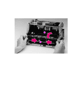
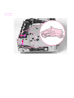
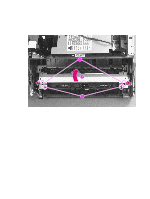
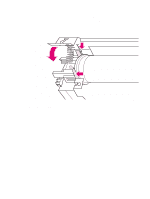
To reinstall The Fuser Pressure Plate is kept in place by four locking mechanisms in each corner. Place the rear slits in the plate over the rear brackets that hold the Fusing Assembly (Figure 6-12, callout 1). Lower the plate over the retaining clips, pressing on both sides of the Fuser Pressure Plate (Figure 6-12, callout, 2). It is important that the spring is placed over the positioning pin (callout 3) because inadequate pressure will cause fusing problems. Replace the screws. Figure 6-12 Fuser Pressure Plate replacement EN Internal assemblies 83
-
 1
1 -
2
-
3
-
4
-
5
-
6
-
7
-
8
-
9
-
10
-
11
-
12
-
13
-
14
-
15
-
16
-
17
-
18
-
19
-
20
-
21
-
22
-
23
-
24
-
25
-
26
-
27
-
28
-
29
-
30
-
31
-
32
-
33
-
34
-
35
-
36
-
37
-
38
-
39
-
40
-
41
-
42
-
43
-
44
-
45
-
46
-
47
-
48
-
49
-
50
-
51
-
52
-
53
-
54
-
55
-
56
-
57
-
58
-
59
-
60
-
61
-
62
-
63
-
64
-
65
-
66
-
67
-
68
-
69
-
70
-
71
-
72
-
73
-
74
-
75
-
76
-
77
-
78
-
79
-
 80
80 -
 81
81 -
 82
82 -
 83
83 -
 84
84 -
 85
85 -
 86
86 -
 87
87 -
 88
88 -
 89
89 -
 90
90 -
91
-
92
-
93
-
94
-
95
-
96
-
97
-
98
-
99
-
100
-
101
-
102
-
103
-
104
-
105
-
106
-
107
-
108
-
109
-
110
-
111
-
112
-
113
-
114
-
115
-
116
-
117
-
118
-
119
-
120
-
121
-
122
-
123
-
124
-
125
-
126
-
127
-
128
-
129
-
130
-
131
-
132
-
133
-
134
-
135
-
136
-
137
-
138
-
139
-
140
-
141
-
142
-
143
-
144
-
145
-
146
-
147
-
148
-
149
-
150
-
151
-
152
-
153
-
154
-
155
-
156
-
157
-
158
-
159
-
160
-
161
-
162
-
163
-
164
-
165
-
166
-
167
-
168
-
169
-
170
-
171
-
172
-
173
-
174
-
175
-
176
-
177
-
178
-
179
-
180
-
181
-
182
-
183
-
184
-
185
-
186
-
187
-
188
-
189
-
190
-
191
-
192
-
193
-
194
 |
 |

EN
Internal assemblies
83
To reinstall
The Fuser Pressure Plate is kept in place by four locking mechanisms in each corner. Place the rear
slits in the plate over the rear brackets that hold the Fusing Assembly (Figure 6-12, callout 1). Lower
the plate over the retaining clips, pressing on both sides of the Fuser Pressure Plate (Figure 6-12,
callout, 2). It is important that the spring is placed over the positioning pin (callout 3) because
inadequate pressure will cause fusing problems. Replace the screws.
Figure
6-12
Fuser Pressure Plate replacement