HP LaserJet 6p/mp Service Manual - Page 90
Face-Up/Face-Down Lever
 |
View all HP LaserJet 6p/mp manuals
Add to My Manuals
Save this manual to your list of manuals |
Page 90 highlights
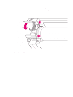
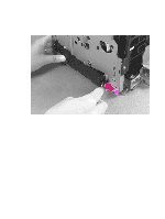
Note Face-Up/Face-Down Lever 1 Remove Printer Covers, Delivery Assembly (Figures 6-9 and 6-10), Fuser Pressure Plate (Figure 6-11), and Heating Element (Figures 6-13 through 6-15), and Pressure Roller (Figure 6-16). 2 Rotate the lever forward 90 degrees (past the spring) and pull it straight out the front of the printer. To reinstall 1 Make sure the lever arm is on the left and is initially pointing downward. 2 Pull the spring forward using needlenose pliers. 3 Slide the short, round tabs into the grooves on the Separation Guide Assembly. The machined ridges on the lever will face you. 4 Release the spring so it falls in place in front of the square tab (Figure 6-17). While the shape of the lever was changed for the HP LaserJet 6L (a stiffening rod was also added), these procedures for Face-Up/Face-Down Lever removal remain unchanged. Figure 6-17 shows the lever from an HP LaserJet 5L. Figure 6-17 Face-Up/Face-Down Lever replacement Note You can tell when the lever is in place because there are two plastic grooves that fit precisely in front of the Exit Rollers, and you should be able to feel the spring's release mechanism. 88 Removal and replacement EN
-
 1
1 -
2
-
3
-
4
-
5
-
6
-
7
-
8
-
9
-
10
-
11
-
12
-
13
-
14
-
15
-
16
-
17
-
18
-
19
-
20
-
21
-
22
-
23
-
24
-
25
-
26
-
27
-
28
-
29
-
30
-
31
-
32
-
33
-
34
-
35
-
36
-
37
-
38
-
39
-
40
-
41
-
42
-
43
-
44
-
45
-
46
-
47
-
48
-
49
-
50
-
51
-
52
-
53
-
54
-
55
-
56
-
57
-
58
-
59
-
60
-
61
-
62
-
63
-
64
-
65
-
66
-
67
-
68
-
69
-
70
-
71
-
72
-
73
-
74
-
75
-
76
-
77
-
78
-
79
-
80
-
81
-
82
-
83
-
84
-
 85
85 -
 86
86 -
 87
87 -
 88
88 -
 89
89 -
 90
90 -
 91
91 -
 92
92 -
 93
93 -
 94
94 -
 95
95 -
96
-
97
-
98
-
99
-
100
-
101
-
102
-
103
-
104
-
105
-
106
-
107
-
108
-
109
-
110
-
111
-
112
-
113
-
114
-
115
-
116
-
117
-
118
-
119
-
120
-
121
-
122
-
123
-
124
-
125
-
126
-
127
-
128
-
129
-
130
-
131
-
132
-
133
-
134
-
135
-
136
-
137
-
138
-
139
-
140
-
141
-
142
-
143
-
144
-
145
-
146
-
147
-
148
-
149
-
150
-
151
-
152
-
153
-
154
-
155
-
156
-
157
-
158
-
159
-
160
-
161
-
162
-
163
-
164
-
165
-
166
-
167
-
168
-
169
-
170
-
171
-
172
-
173
-
174
-
175
-
176
-
177
-
178
-
179
-
180
-
181
-
182
-
183
-
184
-
185
-
186
-
187
-
188
-
189
-
190
-
191
-
192
-
193
-
194
 |
 |
