HP OMEN 17-cb0000 Maintenance and Service Guide - Page 54
Heat sink/fan assembly, Remove the power connector cable from the routing channel in the left fan
 |
View all HP OMEN 17-cb0000 manuals
Add to My Manuals
Save this manual to your list of manuals |
Page 54 highlights
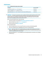
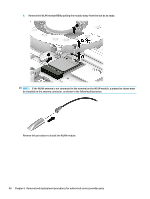
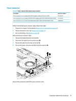
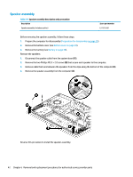
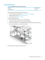
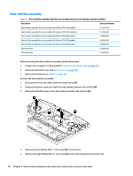
Heat sink/fan assembly Table 6-7 Heat sink/fan assembly, thermal pad, and thermal grease descriptions and part numbers Description Spare part number Heat sink/fan assembly for use in models with GeForce GTX 1660 graphics L57367-001 Heat sink/fan assembly for use in models with GeForce GTX 1660Ti graphics L57366-001 Heat sink/fan assembly for use in models with GeForce GTX 2060 graphics L62864-001 Heat sink/fan assembly for use in models with GeForce GTX 2070 graphics L62865-001 Heat sink/fan assembly for use in models with GeForce GTX 2080 graphics L62866-001 Thermal grease L65268-001 Thermal pad kit L57444-001 Before removing the heat sink/fan assembly, follow these steps: 1. Prepare the computer for disassembly (Preparation for disassembly on page 29). 2. Remove the bottom cover (see Bottom cover on page 30). 3. Remove the battery (see Battery on page 38). Remove the heat sink/fan assembly: 1. Disconnect the two fan cables from the system board (1). 2. Remove the power connector cable from the routing channel in the left fan (2). 3. Remove the WLAN antenna from the routing channel in the right fan (3). 4. Remove the two Phillips M2.0 × 5.0 screws (1) from each fan. 5. Remove the eight Phillips M2.0 × 3.0 screws (2) in the order indicated on the heat sink. 44 Chapter 6 Removal and replacement procedures for authorized service provider parts
-
 1
1 -
2
-
3
-
4
-
5
-
6
-
7
-
8
-
9
-
10
-
11
-
12
-
13
-
14
-
15
-
16
-
17
-
18
-
19
-
20
-
21
-
22
-
23
-
24
-
25
-
26
-
27
-
28
-
29
-
30
-
31
-
32
-
33
-
34
-
35
-
36
-
37
-
38
-
39
-
40
-
41
-
42
-
43
-
44
-
45
-
46
-
47
-
48
-
 49
49 -
 50
50 -
 51
51 -
 52
52 -
 53
53 -
 54
54 -
 55
55 -
 56
56 -
 57
57 -
 58
58 -
 59
59 -
60
-
61
-
62
-
63
-
64
-
65
-
66
-
67
-
68
-
69
-
70
-
71
-
72
-
73
-
74
-
75
-
76
-
77
-
78
-
79
-
80
-
81
-
82
-
83
-
84
-
85
-
86
 |
 |
