HP OMEN 17-cb0000 Maintenance and Service Guide - Page 61
Thermal sensor board, Remove the system board see
 |
View all HP OMEN 17-cb0000 manuals
Add to My Manuals
Save this manual to your list of manuals |
Page 61 highlights
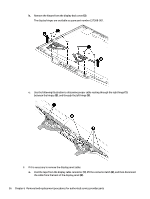
Thermal sensor board NOTE: The thermal sensor board spare part kit does not include the cable. The cable is available as spare part number L57365-001. Table 6-11 Thermal sensor board description and part number Description Spare part number Thermal sensor board L57372-001 Before removing the thermal sensor board, follow these steps: 1. Prepare the computer for disassembly (Preparation for disassembly on page 29). 2. Remove the bottom cover (see Bottom cover on page 30). 3. Remove the battery (see Battery on page 38). 4. Remove the solid-state drive (see Solid-state drive and Optane memory module on page 32). 5. Remove the fan/heat sink (see Heat sink/fan assembly on page 44). 6. Remove the system board (see System board on page 49). Remove the thermal sensor board: 1. Disconnect the cable from the ZIF connector on the sensor board (1). 2. Remove the two Phillips M2.0 × 3.0 screws (2) that secure the sensor board to the computer. 3. Remove the thermal sensor board from the computer (3). Reverse this procedure to install the thermal sensor board. Component replacement procedures 51
-
 1
1 -
2
-
3
-
4
-
5
-
6
-
7
-
8
-
9
-
10
-
11
-
12
-
13
-
14
-
15
-
16
-
17
-
18
-
19
-
20
-
21
-
22
-
23
-
24
-
25
-
26
-
27
-
28
-
29
-
30
-
31
-
32
-
33
-
34
-
35
-
36
-
37
-
38
-
39
-
40
-
41
-
42
-
43
-
44
-
45
-
46
-
47
-
48
-
49
-
50
-
51
-
52
-
53
-
54
-
55
-
 56
56 -
 57
57 -
 58
58 -
 59
59 -
 60
60 -
 61
61 -
 62
62 -
 63
63 -
 64
64 -
 65
65 -
 66
66 -
67
-
68
-
69
-
70
-
71
-
72
-
73
-
74
-
75
-
76
-
77
-
78
-
79
-
80
-
81
-
82
-
83
-
84
-
85
-
86
 |
 |
