HP OMEN 17-cb0000 Maintenance and Service Guide - Page 57
Card reader/USB board, that secures the board to the computer.
 |
View all HP OMEN 17-cb0000 manuals
Add to My Manuals
Save this manual to your list of manuals |
Page 57 highlights
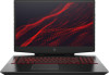
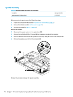
Card reader/USB board NOTE: The card reader/USB board cable is available as spare part number L57363-001. Table 6-8 Card reader board description and part number Description Spare part number Card reader/USB board L57370-001 Before removing the card reader/USB board, follow these steps: 1. Prepare the computer for disassembly (Preparation for disassembly on page 29). 2. Remove the bottom cover (see Bottom cover on page 30). 3. Remove the battery (see Battery on page 38). 4. Remove the fan/heat sink (see Heat sink/fan assembly on page 44). Remove the card reader/USB board: 1. Disconnect the cable from the ZIF connector on the card reader/USB board (1). 2. Remove the Phillips M2.0 × 3.5 screw (2) that secures the board to the computer. 3. Lift the side of the board up, and then pull board up and into the computer to remove it (3). Reverse this procedure to install the card reader/USB board. Component replacement procedures 47
-
 1
1 -
2
-
3
-
4
-
5
-
6
-
7
-
8
-
9
-
10
-
11
-
12
-
13
-
14
-
15
-
16
-
17
-
18
-
19
-
20
-
21
-
22
-
23
-
24
-
25
-
26
-
27
-
28
-
29
-
30
-
31
-
32
-
33
-
34
-
35
-
36
-
37
-
38
-
39
-
40
-
41
-
42
-
43
-
44
-
45
-
46
-
47
-
48
-
49
-
50
-
51
-
 52
52 -
 53
53 -
 54
54 -
 55
55 -
 56
56 -
 57
57 -
 58
58 -
 59
59 -
 60
60 -
 61
61 -
 62
62 -
63
-
64
-
65
-
66
-
67
-
68
-
69
-
70
-
71
-
72
-
73
-
74
-
75
-
76
-
77
-
78
-
79
-
80
-
81
-
82
-
83
-
84
-
85
-
86
 |
 |
