HP Pavilion 15-au600 Maintenance and Service Guide - Page 37
Removal and replacement procedures for Customer Self-Repair parts, Component replacement procedures
 |
View all HP Pavilion 15-au600 manuals
Add to My Manuals
Save this manual to your list of manuals |
Page 37 highlights
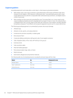
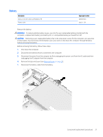
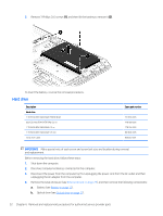
5 Removal and replacement procedures for Customer Self-Repair parts This chapter provides removal and replacement procedures for Customer Self-Repair parts. NOTE: The Customer Self-Repair program is not available in all locations. Installing a part not supported by the Customer Self-Repair program may void your warranty. Check your warranty to determine if Customer SelfRepair is supported in your location. Component replacement procedures NOTE: Details about your computer, including model, serial number, product key, and length of warranty, are on the service tag at the bottom of your computer. See Locating system information on page 14 for details. NOTE: HP continually improves and changes product parts. For complete and current information on supported parts for your computer, go to http://partsurfer.hp.com, select your country or region, and then follow the on-screen instructions. One screw must be removed, replaced, and/or loosened when servicing Customer Self-Repair parts. Make special note of each screw size and location during removal and replacement. Optical drive Description Optical drive, SATA DVDSM 9.0mm tray Bezel, optical drive In Natural Silver finish In Onyx Black finish In Modern Gold finish In Cardinal Red finish In Sport Purple finish In Dragonfly Blue finish In Blizzard White finish Spare part number 803929-005 856339-001 856340-001 856341-001 856342-001 856343-001 856344-001 856345-001 IMPORTANT: Make special note of each screw and screw lock size and location during removal and replacement. Before removing the optical drive, follow these steps: 1. Shut down the computer. 2. Disconnect all external devices connected to the computer. Component replacement procedures 27
-
 1
1 -
2
-
3
-
4
-
5
-
6
-
7
-
8
-
9
-
10
-
11
-
12
-
13
-
14
-
15
-
16
-
17
-
18
-
19
-
20
-
21
-
22
-
23
-
24
-
25
-
26
-
27
-
28
-
29
-
30
-
31
-
 32
32 -
 33
33 -
 34
34 -
 35
35 -
 36
36 -
 37
37 -
 38
38 -
 39
39 -
 40
40 -
 41
41 -
 42
42 -
43
-
44
-
45
-
46
-
47
-
48
-
49
-
50
-
51
-
52
-
53
-
54
-
55
-
56
-
57
-
58
-
59
-
60
-
61
-
62
-
63
-
64
-
65
-
66
-
67
-
68
-
69
-
70
-
71
-
72
-
73
-
74
-
75
-
76
-
77
-
78
-
79
-
80
-
81
-
82
-
83
-
84
-
85
-
86
-
87
-
88
-
89
-
90
-
91
-
92
-
93
-
94
 |
 |