HP Pavilion 15-au600 Maintenance and Service Guide - Page 57
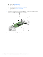
remove the cable, which is held with tape, remove 1 Phillips screw
 |
View all HP Pavilion 15-au600 manuals
Add to My Manuals
Save this manual to your list of manuals |
Page 57 highlights
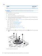
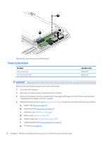
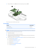
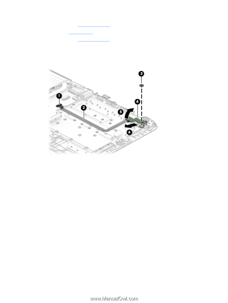
h. Heat sink (see Heat sink on page 43). i. Fan (see Fan on page 42). j. I/O board (see I/O board on page 45). Remove the power button board: ▲ Disconnect the zero-insertion force (ZIF) connector (1), remove the cable, which is held with tape (2), remove 1 Phillips screw (3), slide the power button board (4), lift it at an angle (5), and then remove it (6). Reverse this procedure to install the power button board. Component replacement procedures 47
-
 1
1 -
2
-
3
-
4
-
5
-
6
-
7
-
8
-
9
-
10
-
11
-
12
-
13
-
14
-
15
-
16
-
17
-
18
-
19
-
20
-
21
-
22
-
23
-
24
-
25
-
26
-
27
-
28
-
29
-
30
-
31
-
32
-
33
-
34
-
35
-
36
-
37
-
38
-
39
-
40
-
41
-
42
-
43
-
44
-
45
-
46
-
47
-
48
-
49
-
50
-
51
-
 52
52 -
 53
53 -
 54
54 -
 55
55 -
 56
56 -
 57
57 -
 58
58 -
 59
59 -
 60
60 -
 61
61 -
 62
62 -
63
-
64
-
65
-
66
-
67
-
68
-
69
-
70
-
71
-
72
-
73
-
74
-
75
-
76
-
77
-
78
-
79
-
80
-
81
-
82
-
83
-
84
-
85
-
86
-
87
-
88
-
89
-
90
-
91
-
92
-
93
-
94
 |
 |
h.
Heat sink (see
Heat sink
on page
43
).
i.
Fan (see
Fan
on page
42
).
j.
I/O board (see
I/O board
on page
45
).
Remove the power button board:
▲
Disconnect the zero-insertion force (ZIF) connector
(1)
, remove the cable, which is held with tape
(2)
,
remove 1 Phillips screw
(3)
, slide the power button board
(4)
, lift it at an angle
(5)
, and then remove it
(6)
.
Reverse this procedure to install the power button board.
Component replacement procedures
47