HP Pavilion 15-au600 Maintenance and Service Guide - Page 38
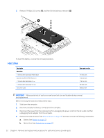
Remove 1 Phillips 2.0x2.5 screw, Remove the optical drive
 |
View all HP Pavilion 15-au600 manuals
Add to My Manuals
Save this manual to your list of manuals |
Page 38 highlights
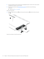
3. Disconnect the power from the computer by first unplugging the power cord from the AC outlet and then unplugging the AC adapter from the computer. 4. Remove the base enclosure (see Base enclosure on page 29), and then remove the following components: ▲ Battery (see Battery on page 31). Remove the optical drive: ▲ Remove 1 Phillips 2.0x2.5 screw (1), push the optical drive eject button (2), and then remove the optical drive (3). Reverse this procedure to install the optical drive. 28 Chapter 5 Removal and replacement procedures for Customer Self-Repair parts
-
 1
1 -
2
-
3
-
4
-
5
-
6
-
7
-
8
-
9
-
10
-
11
-
12
-
13
-
14
-
15
-
16
-
17
-
18
-
19
-
20
-
21
-
22
-
23
-
24
-
25
-
26
-
27
-
28
-
29
-
30
-
31
-
32
-
 33
33 -
 34
34 -
 35
35 -
 36
36 -
 37
37 -
 38
38 -
 39
39 -
 40
40 -
 41
41 -
 42
42 -
 43
43 -
44
-
45
-
46
-
47
-
48
-
49
-
50
-
51
-
52
-
53
-
54
-
55
-
56
-
57
-
58
-
59
-
60
-
61
-
62
-
63
-
64
-
65
-
66
-
67
-
68
-
69
-
70
-
71
-
72
-
73
-
74
-
75
-
76
-
77
-
78
-
79
-
80
-
81
-
82
-
83
-
84
-
85
-
86
-
87
-
88
-
89
-
90
-
91
-
92
-
93
-
94
 |
 |
3.
Disconnect the power from the computer by
first
unplugging the power cord from the AC outlet and then
unplugging the AC adapter from the computer.
4.
Remove the base enclosure (see
Base enclosure
on page
29
), and then remove the following
components:
▲
Battery (see
Battery
on page
31
).
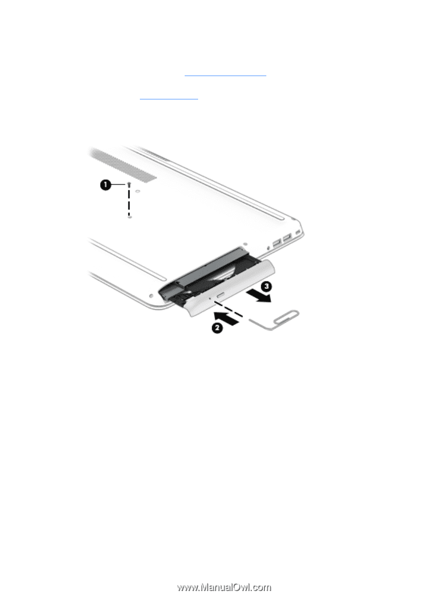
Remove the optical drive:
▲
Remove 1 Phillips 2.0x2.5 screw
(1)
, push the optical drive eject button
(2)
, and then remove the optical
drive
(3)
.
Reverse this procedure to install the optical drive.
28
Chapter 5
Removal and replacement procedures for Customer Self-Repair parts