HP Pavilion 15-au600 Maintenance and Service Guide - Page 52
Fan, WLAN module see
 |
View all HP Pavilion 15-au600 manuals
Add to My Manuals
Save this manual to your list of manuals |
Page 52 highlights
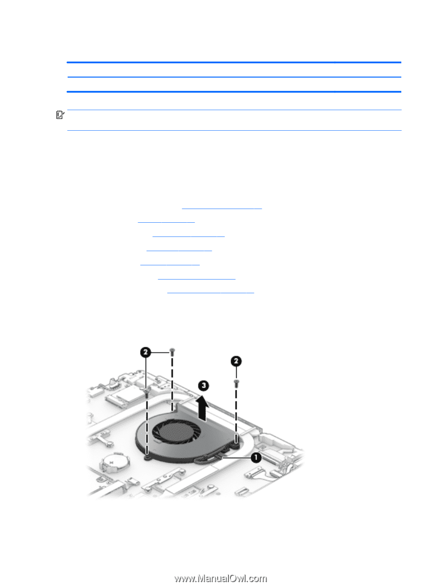
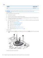
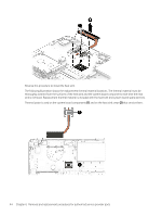
Fan Description Fan Spare part number 856359-001 IMPORTANT: Make special note of each screw and screw lock size and location during removal and replacement. Before removing the fan, follow these steps: 1. Shut down the computer. 2. Disconnect all external devices connected to the computer. 3. Disconnect the power from the computer by first unplugging the power cord from the AC outlet and then unplugging the AC adapter from the computer. 4. Remove the base enclosure (see Base enclosure on page 29), and then remove the following components: a. Battery (see Battery on page 31). b. Optical drive (see Optical drive on page 27). c. Hard drive (see Hard drive on page 32). d. Memory (see Memory on page 35). e. WLAN module (see WLAN module on page 38). f. Display assembly (see Display assembly on page 40). Remove the fan: ▲ Disconnect the fan cable (1), remove 3 Phillips 2x5 screws from the fan (2), and then lift the fan to remove it (3). Reverse this procedure to install the fan. 42 Chapter 6 Removal and replacement procedures for authorized service provider parts
-
 1
1 -
2
-
3
-
4
-
5
-
6
-
7
-
8
-
9
-
10
-
11
-
12
-
13
-
14
-
15
-
16
-
17
-
18
-
19
-
20
-
21
-
22
-
23
-
24
-
25
-
26
-
27
-
28
-
29
-
30
-
31
-
32
-
33
-
34
-
35
-
36
-
37
-
38
-
39
-
40
-
41
-
42
-
43
-
44
-
45
-
46
-
 47
47 -
 48
48 -
 49
49 -
 50
50 -
 51
51 -
 52
52 -
 53
53 -
 54
54 -
 55
55 -
 56
56 -
 57
57 -
58
-
59
-
60
-
61
-
62
-
63
-
64
-
65
-
66
-
67
-
68
-
69
-
70
-
71
-
72
-
73
-
74
-
75
-
76
-
77
-
78
-
79
-
80
-
81
-
82
-
83
-
84
-
85
-
86
-
87
-
88
-
89
-
90
-
91
-
92
-
93
-
94
 |
 |