HP Pavilion 15-au600 Maintenance and Service Guide - Page 62
remove 1 Phillips 2.0x2.5 screw, Disconnect the zero-insertion force ZIF connector
 |
View all HP Pavilion 15-au600 manuals
Add to My Manuals
Save this manual to your list of manuals |
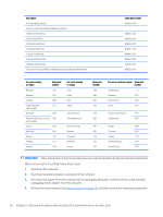
Page 62 highlights
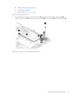
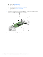
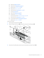
g. Heat sink (see Heat sink on page 43). h. I/O board (see I/O board on page 45). i. Power button board (see Power button board on page 46). j. System board (see System board on page 48). Remove the SD card reader board: ▲ Disconnect the zero-insertion force (ZIF) connector (1), remove 1 Phillips 2.0x2.5 screw (2), remove the board from the clip (3), lift the board (4), and then remove it (5). Reverse this procedure to install the SD card reader board. 52 Chapter 6 Removal and replacement procedures for authorized service provider parts
-
 1
1 -
2
-
3
-
4
-
5
-
6
-
7
-
8
-
9
-
10
-
11
-
12
-
13
-
14
-
15
-
16
-
17
-
18
-
19
-
20
-
21
-
22
-
23
-
24
-
25
-
26
-
27
-
28
-
29
-
30
-
31
-
32
-
33
-
34
-
35
-
36
-
37
-
38
-
39
-
40
-
41
-
42
-
43
-
44
-
45
-
46
-
47
-
48
-
49
-
50
-
51
-
52
-
53
-
54
-
55
-
56
-
 57
57 -
 58
58 -
 59
59 -
 60
60 -
 61
61 -
 62
62 -
 63
63 -
 64
64 -
 65
65 -
 66
66 -
 67
67 -
68
-
69
-
70
-
71
-
72
-
73
-
74
-
75
-
76
-
77
-
78
-
79
-
80
-
81
-
82
-
83
-
84
-
85
-
86
-
87
-
88
-
89
-
90
-
91
-
92
-
93
-
94
 |
 |
g.
Heat sink (see
Heat sink
on page
43
).
h.
I/O board (see
I/O board
on page
45
).
i.
Power button board (see
Power button board
on page
46
).
j.
System board (see
System board
on page
48
).
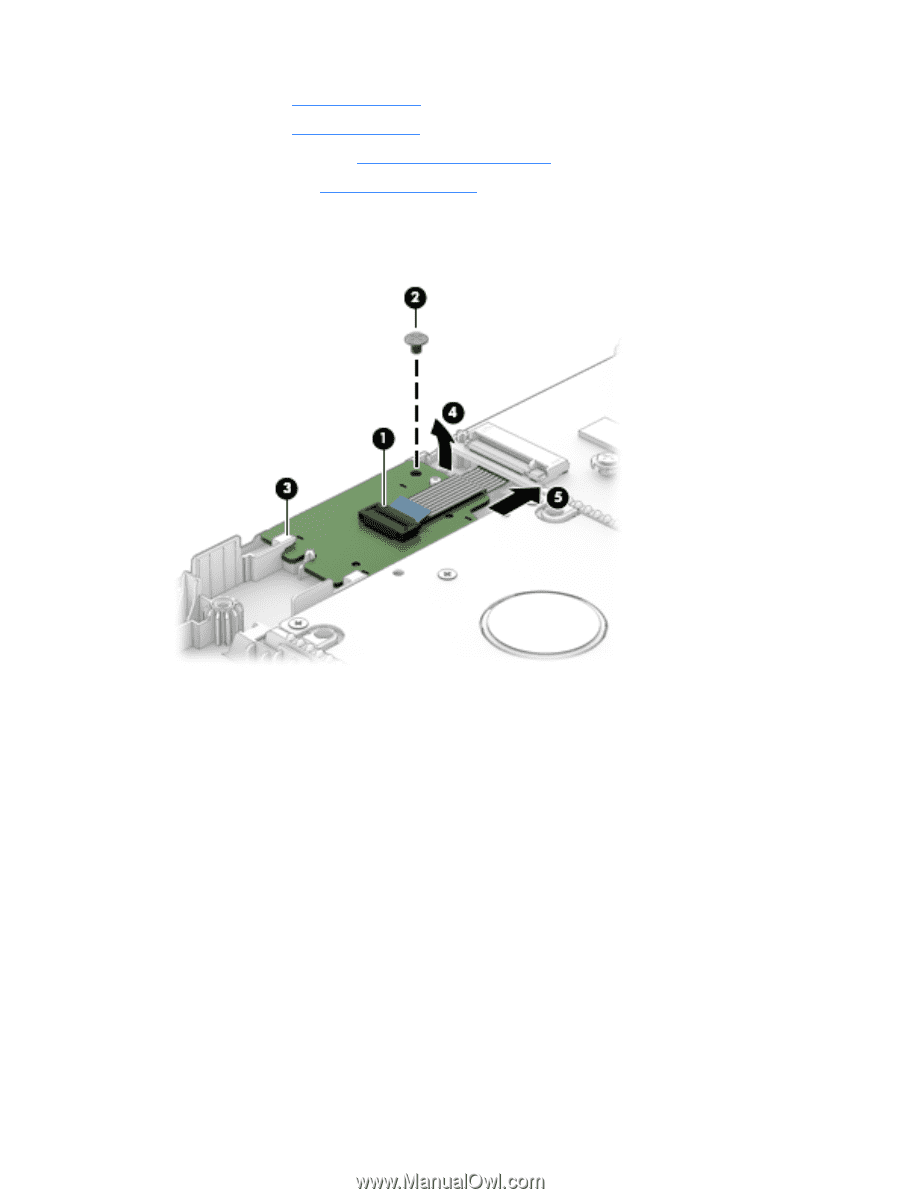
Remove the SD card reader board:
▲
Disconnect the zero-insertion force (ZIF) connector
(1)
, remove 1 Phillips 2.0x2.5 screw
(2)
, remove the
board from the clip
(3)
, lift the board
(4)
, and then remove it
(5)
.
Reverse this procedure to install the SD card reader board.
52
Chapter 6
Removal and replacement procedures for authorized service provider parts