HP Pavilion 15-au600 Maintenance and Service Guide - Page 59
unplugging the power cord from the AC outlet and then
 |
View all HP Pavilion 15-au600 manuals
Add to My Manuals
Save this manual to your list of manuals |
Page 59 highlights
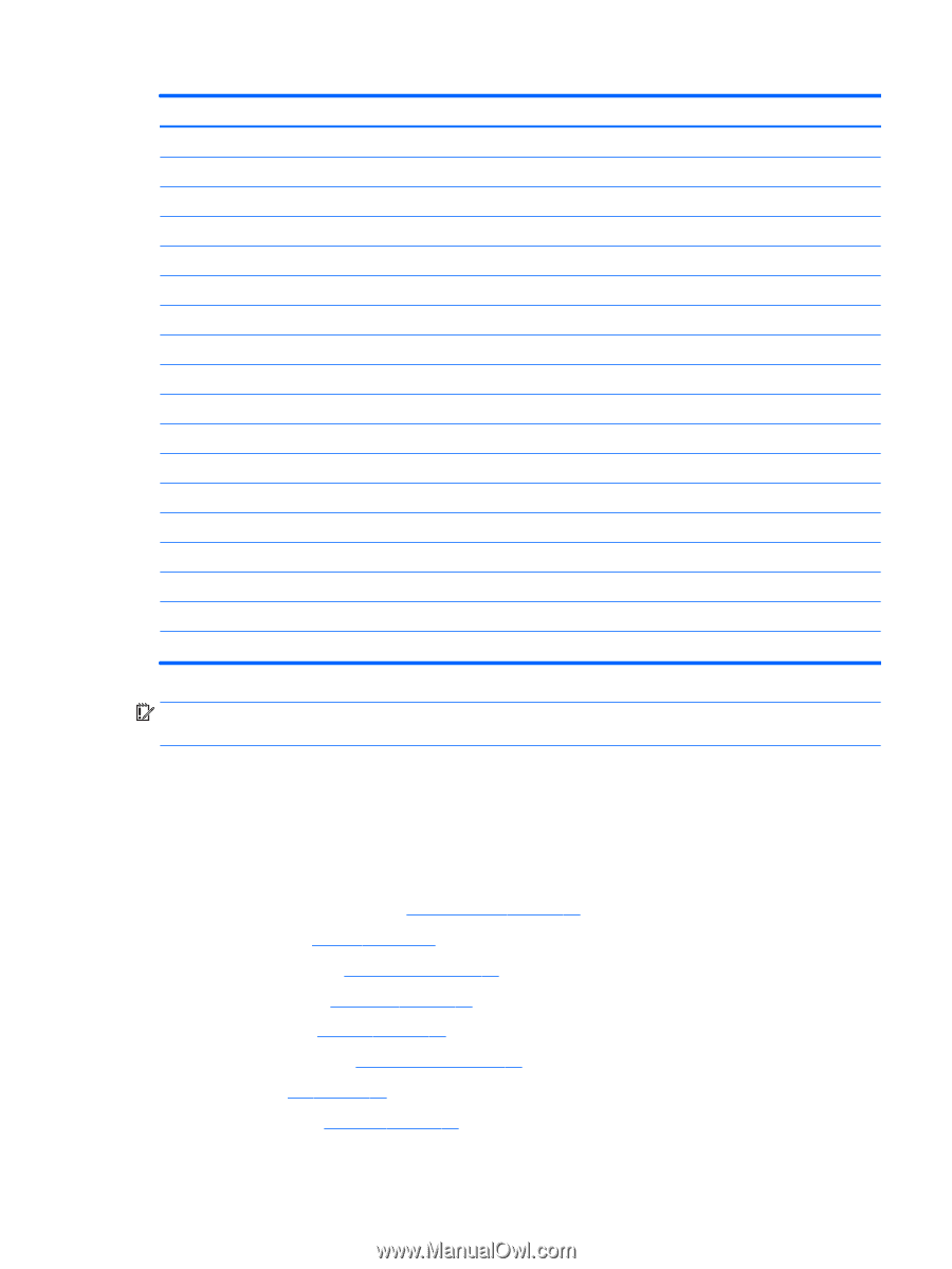
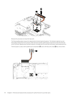
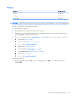
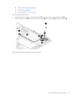
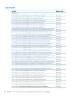
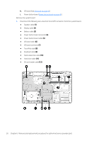
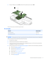
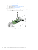
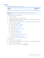
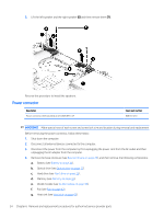
Description Intel i7-7500U fH+S system board 940MX with 2 GB discrete graphics and a non-Windows operating system Intel i7-7500U fH+S system board 940MX with 2 GB discrete graphics and a Windows operating system Intel i5-7200U fH+S system board 940MX with 2 GB discrete graphics and a non-Windows operating system Intel i5-7200U fH+S system board 940MX with 2 GB discrete graphics and a Windows operating system Intel i3-7100U fH+S system board 940MX with 2 GB discrete graphics and a non-Windows operating system Intel i3-7100U fH+S system board 940MX with 2 GB discrete graphics and a Windows operating system Intel i5-7200U fH+S system board 940MX with 2 GB discrete graphics and a non-Windows operating system Intel i5-7200U fH+S system board 940MX with 2 GB discrete graphics and a Windows operating system Intel i7-7500U fH+S system board 940MX with 4GB discrete graphics and a non-Windows operating system Intel i7-7500U fH+S system board 940MX with 4GB discrete graphics and a Windows operating system Intel i5-7200U system board 940MX with 4 GB discrete graphics and a non-Windows operating system Intel i5-7200U system board 940MX with 4 GB discrete graphics and a Windows operating system Intel i5-7200U system board 940MX with 4 GB discrete graphics and a non-Windows operating system Intel i5-7200U system board 940MX with 4 GB discrete graphics and a Windows operating system Intel i5-7200U DfE system board with 2 GB discrete graphics and a Windows operating system Intel i5-7200U DfE system board 940MX with 2 GB discrete graphics and a non-Windows operating system Intel i5-7200U DfE system board with 4 GB discrete graphics and a Windows operating system Intel i5-7200U DfE system board 940MX with 4 GB discrete graphics and a non-Windows operating system Spare part number 901577-001 901577-601 901578-001 901578-601 901579-001 901579-601 901580-001 901580-601 901581-001 901581-601 901582-001 901582-601 901583-001 901583-601 903199-001 903199-601 903200-001 903200-601 IMPORTANT: Make special note of each screw and screw lock size and location during removal and replacement. Before removing the system board, follow these steps: 1. Shut down the computer. 2. Disconnect all external devices connected to the computer. 3. Disconnect the power from the computer by first unplugging the power cord from the AC outlet and then unplugging the AC adapter from the computer. 4. Remove the base enclosure (see Base enclosure on page 29), and then remove the following components: a. Battery (see Battery on page 31). b. Optical drive (see Optical drive on page 27). c. Hard drive (see Hard drive on page 32). d. Memory (see Memory on page 35). e. WLAN module (see WLAN module on page 38). f. Fan (see Fan on page 42). g. Heat sink (see Heat sink on page 43). Component replacement procedures 49
-
 1
1 -
2
-
3
-
4
-
5
-
6
-
7
-
8
-
9
-
10
-
11
-
12
-
13
-
14
-
15
-
16
-
17
-
18
-
19
-
20
-
21
-
22
-
23
-
24
-
25
-
26
-
27
-
28
-
29
-
30
-
31
-
32
-
33
-
34
-
35
-
36
-
37
-
38
-
39
-
40
-
41
-
42
-
43
-
44
-
45
-
46
-
47
-
48
-
49
-
50
-
51
-
52
-
53
-
 54
54 -
 55
55 -
 56
56 -
 57
57 -
 58
58 -
 59
59 -
 60
60 -
 61
61 -
 62
62 -
 63
63 -
 64
64 -
65
-
66
-
67
-
68
-
69
-
70
-
71
-
72
-
73
-
74
-
75
-
76
-
77
-
78
-
79
-
80
-
81
-
82
-
83
-
84
-
85
-
86
-
87
-
88
-
89
-
90
-
91
-
92
-
93
-
94
 |
 |