HP Pavilion 15-au600 Maintenance and Service Guide - Page 51
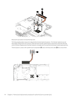
Component replacement procedures, and then remove the display assembly from the base enclosure
 |
View all HP Pavilion 15-au600 manuals
Add to My Manuals
Save this manual to your list of manuals |
Page 51 highlights
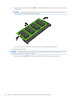
2. Remove 2 Phillips 2.5x6.0 screws from the left hinge and 2 Phillips screws 2.5x6.0 from the right hinge (3). 3. Rotate the display assembly (1), and then remove the display assembly from the base enclosure (2). Reverse this procedure to install the display assembly. Component replacement procedures 41
-
 1
1 -
2
-
3
-
4
-
5
-
6
-
7
-
8
-
9
-
10
-
11
-
12
-
13
-
14
-
15
-
16
-
17
-
18
-
19
-
20
-
21
-
22
-
23
-
24
-
25
-
26
-
27
-
28
-
29
-
30
-
31
-
32
-
33
-
34
-
35
-
36
-
37
-
38
-
39
-
40
-
41
-
42
-
43
-
44
-
45
-
 46
46 -
 47
47 -
 48
48 -
 49
49 -
 50
50 -
 51
51 -
 52
52 -
 53
53 -
 54
54 -
 55
55 -
 56
56 -
57
-
58
-
59
-
60
-
61
-
62
-
63
-
64
-
65
-
66
-
67
-
68
-
69
-
70
-
71
-
72
-
73
-
74
-
75
-
76
-
77
-
78
-
79
-
80
-
81
-
82
-
83
-
84
-
85
-
86
-
87
-
88
-
89
-
90
-
91
-
92
-
93
-
94
 |
 |
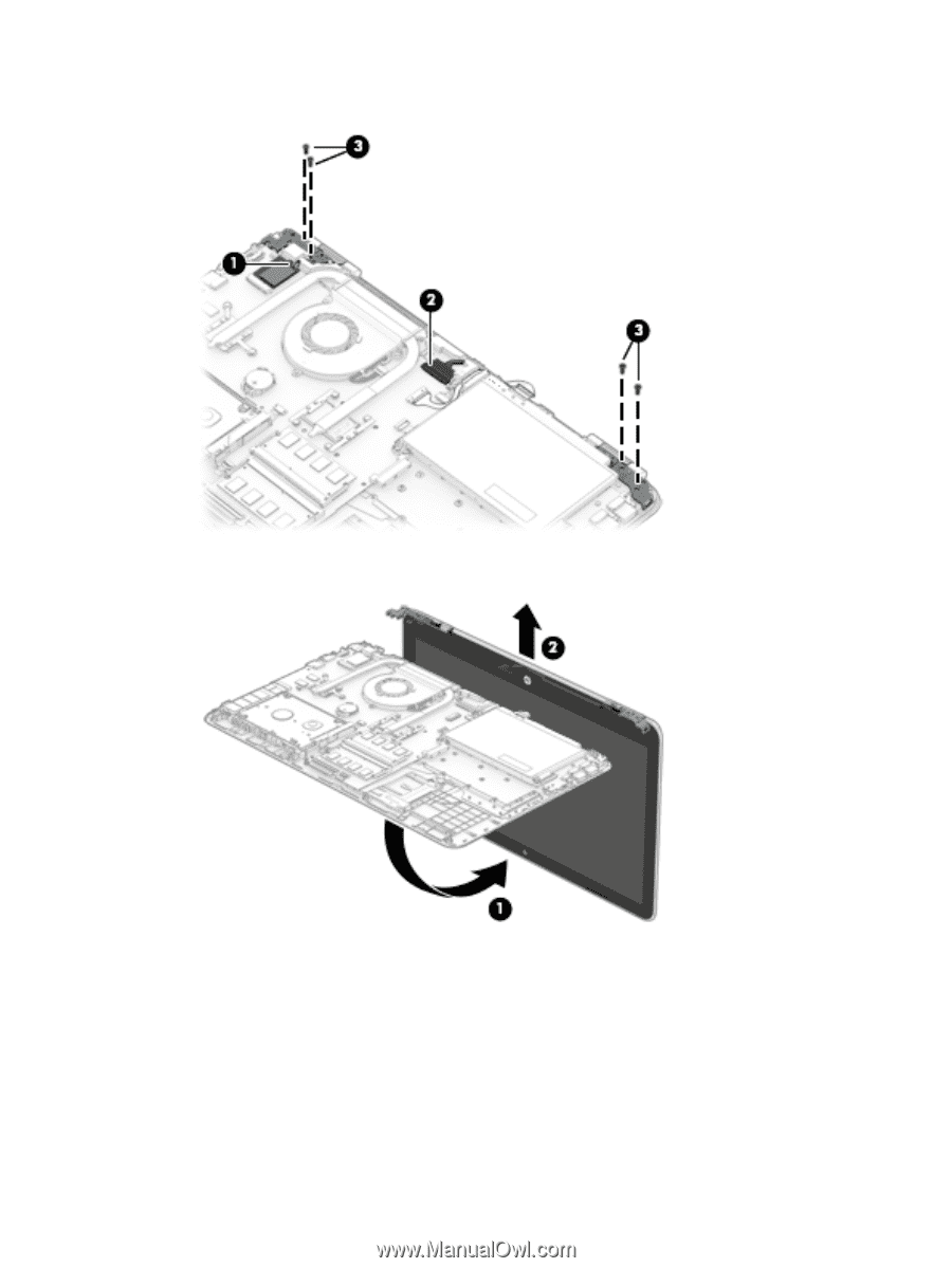
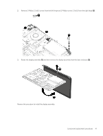
2.
Remove 2 Phillips 2.5x6.0 screws from the left hinge and 2 Phillips screws 2.5x6.0 from the right hinge
(3)
.
3.
Rotate the display assembly
(1)
, and then remove the display assembly from the base enclosure
(2)
.
Reverse this procedure to install the display assembly.
Component replacement procedures
41