HP Pavilion dv9300 HP Pavilion dv9000 Notebook PC - Maintenance and Service Gu - Page 134
by pulling it away from the socket at, Remove the module
 |
View all HP Pavilion dv9300 manuals
Add to My Manuals
Save this manual to your list of manuals |
Page 134 highlights
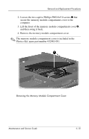
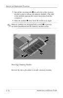
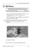
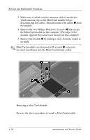
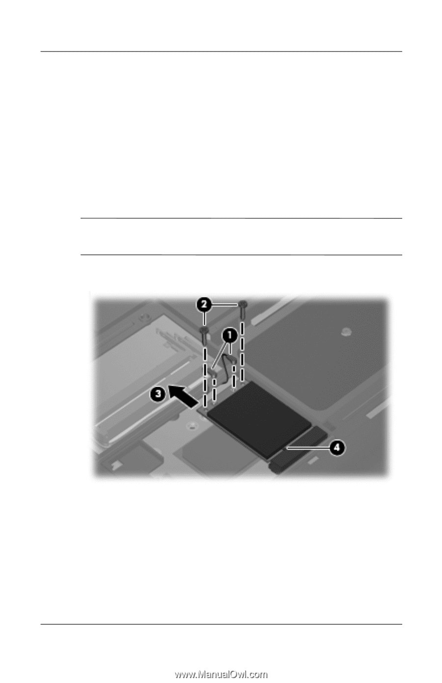
Removal and Replacement Procedures 3. Make note of which wireless antenna cable is attached to which antenna clip on the Mini Card module before disconnecting the cables. Then disconnect the cables 1 from the module. 4. Remove the two Phillips PM2.0×11.0 screws 2 that secure the Mini Card module to the computer. (The edge of the module opposite the socket rises away from the computer). 5. Remove the module 3 by pulling it away from the socket at an angle. ✎ Mini Card modules are designed with a notch 4 to prevent incorrect installation into the Mini Card module socket. Removing a Mini Card Module Reverse the above procedure to install a Mini Card module. 5-18 Maintenance and Service Guide
-
 1
1 -
2
-
3
-
4
-
5
-
6
-
7
-
8
-
9
-
10
-
11
-
12
-
13
-
14
-
15
-
16
-
17
-
18
-
19
-
20
-
21
-
22
-
23
-
24
-
25
-
26
-
27
-
28
-
29
-
30
-
31
-
32
-
33
-
34
-
35
-
36
-
37
-
38
-
39
-
40
-
41
-
42
-
43
-
44
-
45
-
46
-
47
-
48
-
49
-
50
-
51
-
52
-
53
-
54
-
55
-
56
-
57
-
58
-
59
-
60
-
61
-
62
-
63
-
64
-
65
-
66
-
67
-
68
-
69
-
70
-
71
-
72
-
73
-
74
-
75
-
76
-
77
-
78
-
79
-
80
-
81
-
82
-
83
-
84
-
85
-
86
-
87
-
88
-
89
-
90
-
91
-
92
-
93
-
94
-
95
-
96
-
97
-
98
-
99
-
100
-
101
-
102
-
103
-
104
-
105
-
106
-
107
-
108
-
109
-
110
-
111
-
112
-
113
-
114
-
115
-
116
-
117
-
118
-
119
-
120
-
121
-
122
-
123
-
124
-
125
-
126
-
127
-
128
-
 129
129 -
 130
130 -
 131
131 -
 132
132 -
 133
133 -
 134
134 -
 135
135 -
 136
136 -
 137
137 -
 138
138 -
 139
139 -
140
-
141
-
142
-
143
-
144
-
145
-
146
-
147
-
148
-
149
-
150
-
151
-
152
-
153
-
154
-
155
-
156
-
157
-
158
-
159
-
160
-
161
-
162
-
163
-
164
-
165
-
166
-
167
-
168
-
169
-
170
-
171
-
172
-
173
-
174
-
175
-
176
-
177
-
178
-
179
-
180
-
181
-
182
-
183
-
184
-
185
-
186
-
187
-
188
-
189
-
190
-
191
-
192
-
193
-
194
-
195
-
196
-
197
-
198
-
199
-
200
-
201
-
202
-
203
-
204
-
205
-
206
-
207
-
208
-
209
-
210
-
211
-
212
-
213
-
214
-
215
-
216
-
217
-
218
-
219
-
220
-
221
-
222
-
223
-
224
-
225
-
226
-
227
-
228
-
229
-
230
-
231
-
232
-
233
-
234
-
235
-
236
-
237
-
238
-
239
-
240
-
241
-
242
-
243
-
244
-
245
-
246
-
247
-
248
-
249
-
250
-
251
-
252
-
253
-
254
-
255
-
256
-
257
-
258
-
259
-
260
-
261
-
262
-
263
-
264
-
265
-
266
-
267
-
268
-
269
-
270
-
271
-
272
-
273
-
274
-
275
-
276
-
277
-
278
-
279
-
280
-
281
-
282
-
283
-
284
-
285
-
286
-
287
-
288
-
289
-
290
-
291
-
292
-
293
-
294
-
295
-
296
-
297
-
298
-
299
-
300
-
301
-
302
-
303
 |
 |
5–18
Maintenance and Service Guide
Removal and Replacement Procedures
3. Make note of which wireless antenna cable is attached to
which antenna clip on the Mini Card module before
disconnecting the cables. Then disconnect the cables
1
from
the module.
4. Remove the two Phillips PM2.0×11.0 screws
2
that secure
the Mini Card module to the computer. (The edge of the
module opposite the socket rises away from the computer).
5. Remove the module
3
by pulling it away from the socket at
an angle.
✎
Mini Card modules are designed with a notch
4
to prevent
incorrect installation into the Mini Card module socket.
Removing a Mini Card Module
Reverse the above procedure to install a Mini Card module.