HP Pavilion dv9300 HP Pavilion dv9000 Notebook PC - Maintenance and Service Gu - Page 196
Fan/Heat Sink Assembly, Fan/Heat Sink Assembly Spare Part Number Information
 |
View all HP Pavilion dv9300 manuals
Add to My Manuals
Save this manual to your list of manuals |
Page 196 highlights
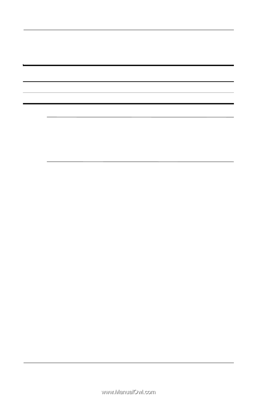
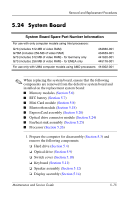
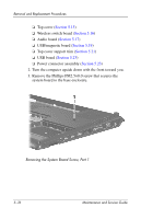
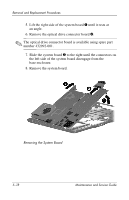
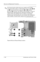
Removal and Replacement Procedures 5.25 Fan/Heat Sink Assembly Fan/Heat Sink Assembly Spare Part Number Information For use only with computer models using Intel processors For use only with computer models using AMD processors 434678-001 438606-001 ✎ When replacing the fan/heat sink assembly, be sure the display lid switch module is removed from the defective fan/heat sink assembly and installed on the replacement fan/heat sink assembly. Refer to Section 5.22, "Display Lid Switch Module," for display lid switch module removal information. 1. Prepare the computer for disassembly (Section 5.3) and remove the following components: ❏ Hard drive (Section 5.4) ❏ Optical drive (Section 5.9) ❏ Switch cover (Section 5.10) ❏ Keyboard (Section 5.11) ❏ Speaker assembly (Section 5.12) ❏ Display assembly (Section 5.14) ❏ Top cover (Section 5.15) ❏ Wireless switch board (Section 5.16) ❏ Audio board (Section 5.17) ❏ USB/magnetic board (Section 5.19) ❏ Top cover support trim (Section 5.21) ❏ USB board (Section 5.23) ❏ Power connector assembly (Section 5.23) ❏ System board (Section 5.24) 5-80 Maintenance and Service Guide
-
 1
1 -
2
-
3
-
4
-
5
-
6
-
7
-
8
-
9
-
10
-
11
-
12
-
13
-
14
-
15
-
16
-
17
-
18
-
19
-
20
-
21
-
22
-
23
-
24
-
25
-
26
-
27
-
28
-
29
-
30
-
31
-
32
-
33
-
34
-
35
-
36
-
37
-
38
-
39
-
40
-
41
-
42
-
43
-
44
-
45
-
46
-
47
-
48
-
49
-
50
-
51
-
52
-
53
-
54
-
55
-
56
-
57
-
58
-
59
-
60
-
61
-
62
-
63
-
64
-
65
-
66
-
67
-
68
-
69
-
70
-
71
-
72
-
73
-
74
-
75
-
76
-
77
-
78
-
79
-
80
-
81
-
82
-
83
-
84
-
85
-
86
-
87
-
88
-
89
-
90
-
91
-
92
-
93
-
94
-
95
-
96
-
97
-
98
-
99
-
100
-
101
-
102
-
103
-
104
-
105
-
106
-
107
-
108
-
109
-
110
-
111
-
112
-
113
-
114
-
115
-
116
-
117
-
118
-
119
-
120
-
121
-
122
-
123
-
124
-
125
-
126
-
127
-
128
-
129
-
130
-
131
-
132
-
133
-
134
-
135
-
136
-
137
-
138
-
139
-
140
-
141
-
142
-
143
-
144
-
145
-
146
-
147
-
148
-
149
-
150
-
151
-
152
-
153
-
154
-
155
-
156
-
157
-
158
-
159
-
160
-
161
-
162
-
163
-
164
-
165
-
166
-
167
-
168
-
169
-
170
-
171
-
172
-
173
-
174
-
175
-
176
-
177
-
178
-
179
-
180
-
181
-
182
-
183
-
184
-
185
-
186
-
187
-
188
-
189
-
190
-
 191
191 -
 192
192 -
 193
193 -
 194
194 -
 195
195 -
 196
196 -
 197
197 -
 198
198 -
 199
199 -
 200
200 -
 201
201 -
202
-
203
-
204
-
205
-
206
-
207
-
208
-
209
-
210
-
211
-
212
-
213
-
214
-
215
-
216
-
217
-
218
-
219
-
220
-
221
-
222
-
223
-
224
-
225
-
226
-
227
-
228
-
229
-
230
-
231
-
232
-
233
-
234
-
235
-
236
-
237
-
238
-
239
-
240
-
241
-
242
-
243
-
244
-
245
-
246
-
247
-
248
-
249
-
250
-
251
-
252
-
253
-
254
-
255
-
256
-
257
-
258
-
259
-
260
-
261
-
262
-
263
-
264
-
265
-
266
-
267
-
268
-
269
-
270
-
271
-
272
-
273
-
274
-
275
-
276
-
277
-
278
-
279
-
280
-
281
-
282
-
283
-
284
-
285
-
286
-
287
-
288
-
289
-
290
-
291
-
292
-
293
-
294
-
295
-
296
-
297
-
298
-
299
-
300
-
301
-
302
-
303
 |
 |