HP Pavilion m4-1000 HP Pavilion m4 Notebook PC Maintenance and Service Guide - Page 54
Release the ZIF connector, Open the computer.
 |
View all HP Pavilion m4-1000 manuals
Add to My Manuals
Save this manual to your list of manuals |
Page 54 highlights
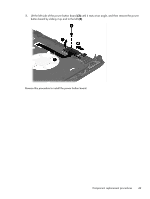
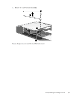
3. Remove the two Phillips PM2.0×2.0 broad head screws (1) in the optical drive bay that secure the top cover to the computer. 4. Remove the two Phillips PM2.5×4.0 screws (2) in the hard drive bay that secure the top cover to the computer. 5. Turn the computer right side, with the front toward you. 6. Open the computer. 7. Release the ZIF connector (1) to which the power button board cable is attached, and then disconnect the power button board cable from the system board. 46 Chapter 6 Removal and replacement procedures for Authorized Service Provider parts
-
 1
1 -
2
-
3
-
4
-
5
-
6
-
7
-
8
-
9
-
10
-
11
-
12
-
13
-
14
-
15
-
16
-
17
-
18
-
19
-
20
-
21
-
22
-
23
-
24
-
25
-
26
-
27
-
28
-
29
-
30
-
31
-
32
-
33
-
34
-
35
-
36
-
37
-
38
-
39
-
40
-
41
-
42
-
43
-
44
-
45
-
46
-
47
-
48
-
 49
49 -
 50
50 -
 51
51 -
 52
52 -
 53
53 -
 54
54 -
 55
55 -
 56
56 -
 57
57 -
 58
58 -
 59
59 -
60
-
61
-
62
-
63
-
64
-
65
-
66
-
67
-
68
-
69
-
70
-
71
-
72
-
73
-
74
-
75
-
76
-
77
-
78
-
79
-
80
-
81
-
82
-
83
-
84
-
85
-
86
-
87
-
88
-
89
-
90
-
91
-
92
-
93
-
94
-
95
-
96
-
97
 |
 |
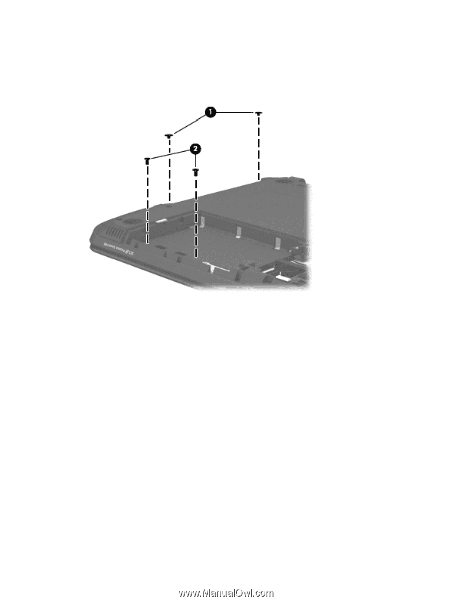
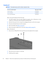
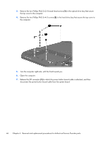
3.
Remove the two Phillips PM2.0×2.0 broad head screws
(1)
in the optical drive bay that secure
the top cover to the computer.
4.
Remove the two Phillips PM2.5×4.0 screws
(2)
in the hard drive bay that secure the top cover to
the computer.
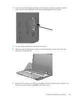
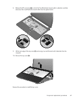
5.
Turn the computer right side, with the front toward you.
6.
Open the computer.
7.
Release the ZIF connector
(1)
to which the power button board cable is attached, and then
disconnect the power button board cable from the system board.
46
Chapter 6
Removal and replacement procedures for Authorized Service Provider parts