HP Pavilion m4-1000 HP Pavilion m4 Notebook PC Maintenance and Service Guide - Page 73
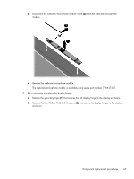
enclosure and right display hinge., Release the wireless antenna cables
 |
View all HP Pavilion m4-1000 manuals
Add to My Manuals
Save this manual to your list of manuals |
Page 73 highlights
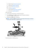
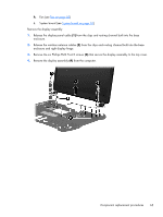
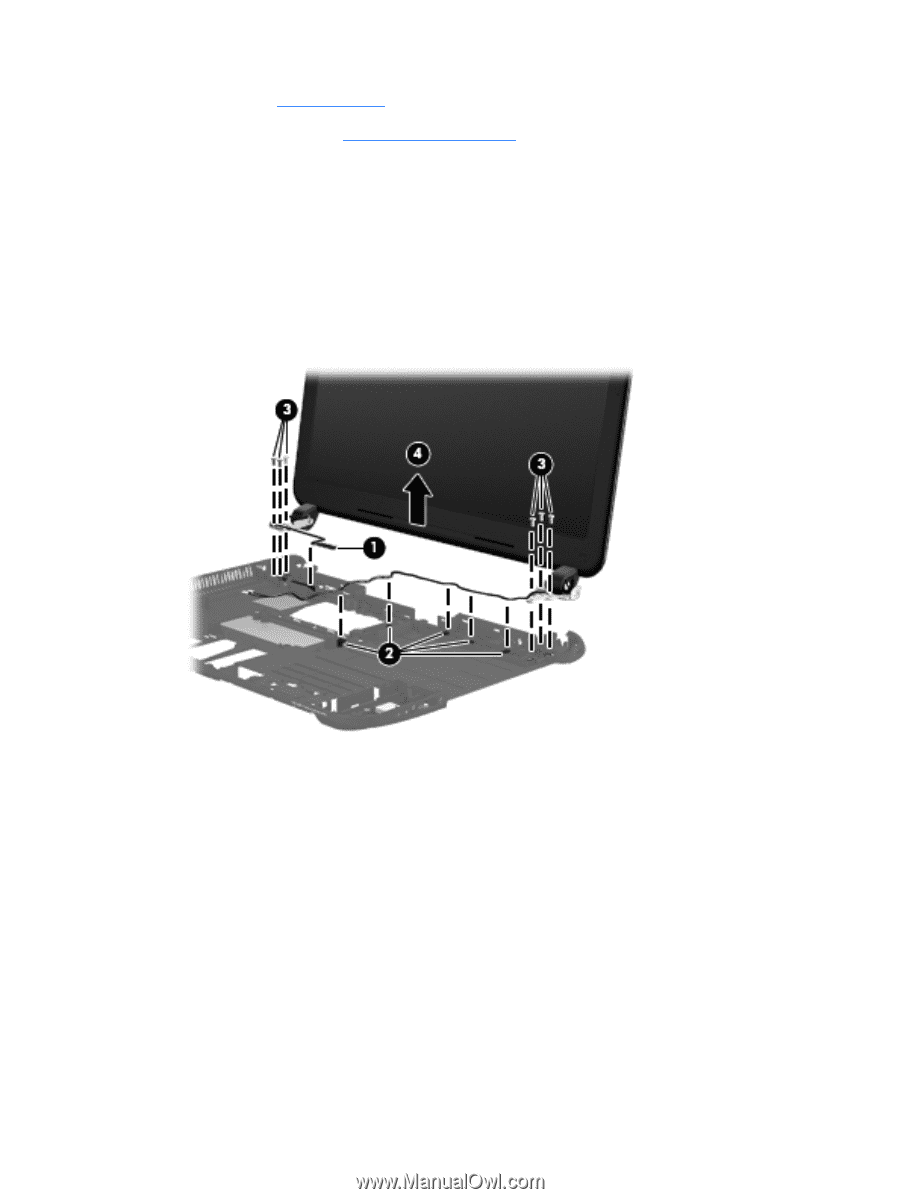
h. Fan (see Fan on page 52) i. System board (see System board on page 55) Remove the display assembly: 1. Release the display panel cable (1) from the clips and routing channel built into the base enclosure. 2. Release the wireless antenna cables (2) from the clips and routing channel built into the base enclosure and right display hinge. 3. Remove the six Phillips PM2.5×4.5 screws (3) that secure the display assembly to the top cover. 4. Remove the display assembly (4) from the computer. Component replacement procedures 65
-
 1
1 -
2
-
3
-
4
-
5
-
6
-
7
-
8
-
9
-
10
-
11
-
12
-
13
-
14
-
15
-
16
-
17
-
18
-
19
-
20
-
21
-
22
-
23
-
24
-
25
-
26
-
27
-
28
-
29
-
30
-
31
-
32
-
33
-
34
-
35
-
36
-
37
-
38
-
39
-
40
-
41
-
42
-
43
-
44
-
45
-
46
-
47
-
48
-
49
-
50
-
51
-
52
-
53
-
54
-
55
-
56
-
57
-
58
-
59
-
60
-
61
-
62
-
63
-
64
-
65
-
66
-
67
-
 68
68 -
 69
69 -
 70
70 -
 71
71 -
 72
72 -
 73
73 -
 74
74 -
 75
75 -
 76
76 -
 77
77 -
 78
78 -
79
-
80
-
81
-
82
-
83
-
84
-
85
-
86
-
87
-
88
-
89
-
90
-
91
-
92
-
93
-
94
-
95
-
96
-
97
 |
 |
h.
Fan (see
Fan
on page
52
)
i.
System board (see
System board
on page
55
)
Remove the display assembly:
1.
Release the display panel cable
(1)
from the clips and routing channel built into the base
enclosure.
2.
Release the wireless antenna cables
(2)
from the clips and routing channel built into the base
enclosure and right display hinge.
3.
Remove the six Phillips PM2.5×4.5 screws
(3)
that secure the display assembly to the top cover.
4.
Remove the display assembly
(4)
from the computer.
Component replacement procedures
65