HP Pavilion m4-1000 HP Pavilion m4 Notebook PC Maintenance and Service Guide - Page 74
CAUTION, Handle the webcam/microphone module with caution. This module has a thin
 |
View all HP Pavilion m4-1000 manuals
Add to My Manuals
Save this manual to your list of manuals |
Page 74 highlights
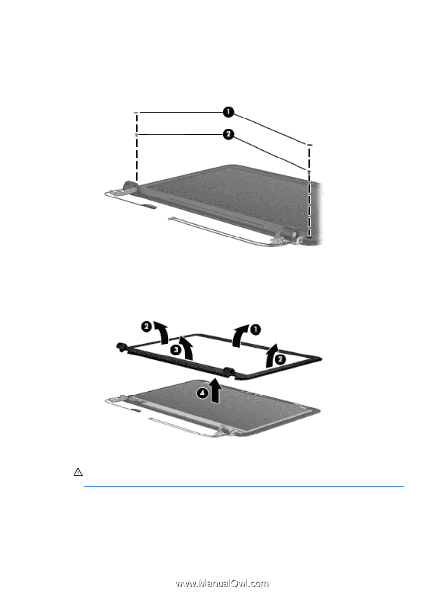
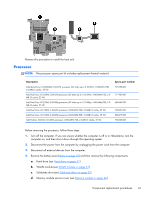
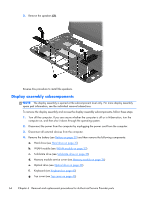
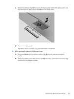
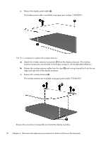
5. If it is necessary to replace the display bezel or any of the display assembly subcomponents: a. Remove the two crew covers (1) and the two Phillips PM2.5×3.5 screws (2) that secure the display bezel to the display assembly. The screw covers are available in the Rubber Kit, spare part number 718441-001. b. Flex the inside edges of the top edge (1), the left and right sides (2), and the bottom edge (3) of the display bezel until the bezel disengages from the display enclosure. c. Remove the display bezel (4). The display bezel is available using spare part number 718427-001. 6. If it is necessary to replace the webcam/microphone module: CAUTION: Handle the webcam/microphone module with caution. This module has a thin profile and is susceptible to damage when not handled carefully. a. Detach the webcam/microphone module (1) from the display enclosure. (The webcam/ microphone module is attached to the display enclosure with double-sided adhesive.) 66 Chapter 6 Removal and replacement procedures for Authorized Service Provider parts
-
 1
1 -
2
-
3
-
4
-
5
-
6
-
7
-
8
-
9
-
10
-
11
-
12
-
13
-
14
-
15
-
16
-
17
-
18
-
19
-
20
-
21
-
22
-
23
-
24
-
25
-
26
-
27
-
28
-
29
-
30
-
31
-
32
-
33
-
34
-
35
-
36
-
37
-
38
-
39
-
40
-
41
-
42
-
43
-
44
-
45
-
46
-
47
-
48
-
49
-
50
-
51
-
52
-
53
-
54
-
55
-
56
-
57
-
58
-
59
-
60
-
61
-
62
-
63
-
64
-
65
-
66
-
67
-
68
-
 69
69 -
 70
70 -
 71
71 -
 72
72 -
 73
73 -
 74
74 -
 75
75 -
 76
76 -
 77
77 -
 78
78 -
 79
79 -
80
-
81
-
82
-
83
-
84
-
85
-
86
-
87
-
88
-
89
-
90
-
91
-
92
-
93
-
94
-
95
-
96
-
97
 |
 |