HP Pavilion m4-1000 HP Pavilion m4 Notebook PC Maintenance and Service Guide - Page 68
the system board components, it may be necessary to move the heat sink from side to side
 |
View all HP Pavilion m4-1000 manuals
Add to My Manuals
Save this manual to your list of manuals |
Page 68 highlights
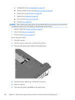
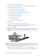
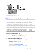
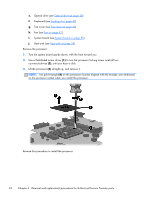
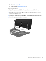
3. Disconnect all external devices from the computer. 4. Remove the battery (see Battery on page 30) and then remove the following components: a. Hard drive (see Hard drive on page 31) b. WLAN module (see WLAN module on page 33) c. Solid-state drive (see Solid-state drive on page 35) d. Memory module service cover (see Memory module on page 36) e. Optical drive (see Optical drive on page 38) f. Keyboard (see Keyboard on page 42) g. Top cover (see Top cover on page 45) h. Fan (see Fan on page 52) i. System board (see System board on page 55) Remove the heat sink: 1. Turn the system board upside down, with the front toward you. 2. Following the 1, 2, 3, 4, 5, 6 sequence stamped into the heat sink, remove the six Phillips PM2.0×4.5 screws (1) that secure the heat sink to the system board. 3. Remove the heat sink (2). NOTE: Due to the adhesive quality of the thermal material located between the heat sink and the system board components, it may be necessary to move the heat sink from side to side to detach it. NOTE: The thermal material must be thoroughly cleaned from the surfaces of the heat sink and the system board components each time the heat sink is removed. Replacement thermal material is included with the heat sink, processor, and system board spare part kits. ● Thermal paste is used on the processor (1) and the heat sink section (2) that services it ● A thermal pad is used on the Northbridge chip (3) and the heat sink section (4) that services it 60 Chapter 6 Removal and replacement procedures for Authorized Service Provider parts
-
 1
1 -
2
-
3
-
4
-
5
-
6
-
7
-
8
-
9
-
10
-
11
-
12
-
13
-
14
-
15
-
16
-
17
-
18
-
19
-
20
-
21
-
22
-
23
-
24
-
25
-
26
-
27
-
28
-
29
-
30
-
31
-
32
-
33
-
34
-
35
-
36
-
37
-
38
-
39
-
40
-
41
-
42
-
43
-
44
-
45
-
46
-
47
-
48
-
49
-
50
-
51
-
52
-
53
-
54
-
55
-
56
-
57
-
58
-
59
-
60
-
61
-
62
-
 63
63 -
 64
64 -
 65
65 -
 66
66 -
 67
67 -
 68
68 -
 69
69 -
 70
70 -
 71
71 -
 72
72 -
 73
73 -
74
-
75
-
76
-
77
-
78
-
79
-
80
-
81
-
82
-
83
-
84
-
85
-
86
-
87
-
88
-
89
-
90
-
91
-
92
-
93
-
94
-
95
-
96
-
97
 |
 |