HP Pavilion m4-1000 HP Pavilion m4 Notebook PC Maintenance and Service Guide - Page 70
to turn the processor locking screw one-half turn, until you hear a click.
 |
View all HP Pavilion m4-1000 manuals
Add to My Manuals
Save this manual to your list of manuals |
Page 70 highlights
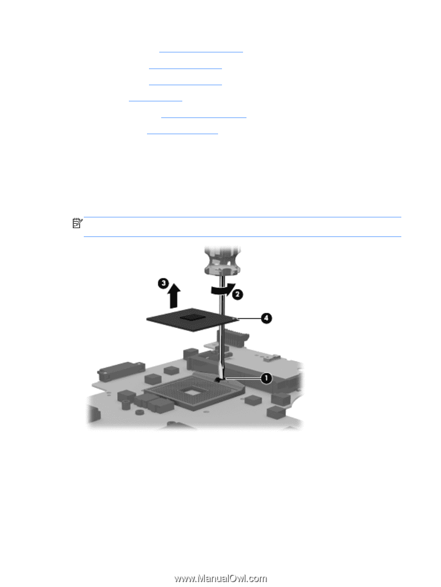
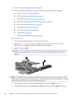
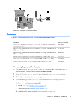
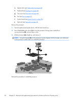
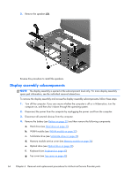
e. Optical drive (see Optical drive on page 38) f. Keyboard (see Keyboard on page 42) g. Top cover (see Top cover on page 45) h. Fan (see Fan on page 52) i. System board (see System board on page 55) j. Heat sink (see Heat sink on page 59) Remove the processor: 1. Turn the system board upside down, with the front toward you. 2. Use a flat-bladed screw driver (1) to turn the processor locking screw one-half turn counterclockwise (2), until you hear a click. 3. Lift the processor (3) straight up, and remove it. NOTE: The gold triangle (4) on the processor must be aligned with the triangle icon embossed on the processor socket when you install the processor. Reverse this procedure to install the processor. 62 Chapter 6 Removal and replacement procedures for Authorized Service Provider parts
-
 1
1 -
2
-
3
-
4
-
5
-
6
-
7
-
8
-
9
-
10
-
11
-
12
-
13
-
14
-
15
-
16
-
17
-
18
-
19
-
20
-
21
-
22
-
23
-
24
-
25
-
26
-
27
-
28
-
29
-
30
-
31
-
32
-
33
-
34
-
35
-
36
-
37
-
38
-
39
-
40
-
41
-
42
-
43
-
44
-
45
-
46
-
47
-
48
-
49
-
50
-
51
-
52
-
53
-
54
-
55
-
56
-
57
-
58
-
59
-
60
-
61
-
62
-
63
-
64
-
 65
65 -
 66
66 -
 67
67 -
 68
68 -
 69
69 -
 70
70 -
 71
71 -
 72
72 -
 73
73 -
 74
74 -
 75
75 -
76
-
77
-
78
-
79
-
80
-
81
-
82
-
83
-
84
-
85
-
86
-
87
-
88
-
89
-
90
-
91
-
92
-
93
-
94
-
95
-
96
-
97
 |
 |