HP Presario CQ45-300 Compaq Presario CQ45 Notebook PC - Maintenance and Servic - Page 75
Camera/microphone module, then unplugging the AC adapter from the computer.
 |
View all HP Presario CQ45-300 manuals
Add to My Manuals
Save this manual to your list of manuals |
Page 75 highlights
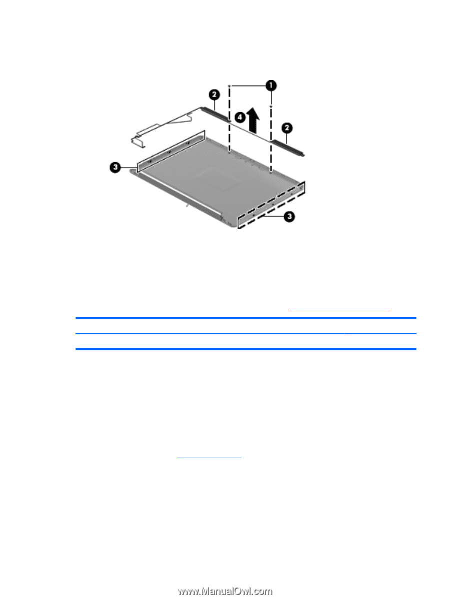
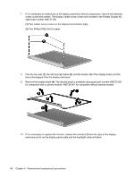
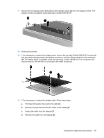
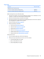
20. Remove the wireless antenna transceivers and cables (4) from the display enclosure. The wireless antenna transceivers and cables are included in the Wireless Antenna Kit, spare part number 489066-001. Reverse this procedure to reassemble and install the display assembly. Camera/microphone module If it has been determined that the camera/microphone module is the component that must be replaced to complete the computer repair, the display assembly does not have to be removed. Follow the procedures in this section to replace the camera module. For information on replacing the display assembly and other display assembly internal components, see Display assembly on page 62. Description Camera/microphone module Spare part number 486734-001 Before removing the camera/microphone module, follow these steps: 1. Shut down the computer. If you are unsure whether the computer is off or in Hibernation, turn the computer on, and then shut it down through the operating system. 2. Disconnect all external devices connected to the computer. 3. Disconnect the power from the computer by first unplugging the power cord from the AC outlet and then unplugging the AC adapter from the computer. 4. Remove the battery (see Battery on page 43). Remove the camera/microphone module: 1. Turn the computer display-side up, with the front toward you. 2. Open the computer as far as it will open. 3. Flex the inside edges of the left and right sides, and then pull outward on the middle of the top edge (1) of the display bezel until the top middle of the bezel disengages from the display enclosure. Component replacement procedures 67
-
 1
1 -
2
-
3
-
4
-
5
-
6
-
7
-
8
-
9
-
10
-
11
-
12
-
13
-
14
-
15
-
16
-
17
-
18
-
19
-
20
-
21
-
22
-
23
-
24
-
25
-
26
-
27
-
28
-
29
-
30
-
31
-
32
-
33
-
34
-
35
-
36
-
37
-
38
-
39
-
40
-
41
-
42
-
43
-
44
-
45
-
46
-
47
-
48
-
49
-
50
-
51
-
52
-
53
-
54
-
55
-
56
-
57
-
58
-
59
-
60
-
61
-
62
-
63
-
64
-
65
-
66
-
67
-
68
-
69
-
 70
70 -
 71
71 -
 72
72 -
 73
73 -
 74
74 -
 75
75 -
 76
76 -
 77
77 -
 78
78 -
 79
79 -
 80
80 -
81
-
82
-
83
-
84
-
85
-
86
-
87
-
88
-
89
-
90
-
91
-
92
-
93
-
94
-
95
-
96
-
97
-
98
-
99
-
100
-
101
-
102
-
103
-
104
-
105
-
106
-
107
-
108
-
109
-
110
-
111
-
112
-
113
-
114
-
115
-
116
-
117
-
118
-
119
-
120
-
121
-
122
-
123
-
124
-
125
-
126
-
127
-
128
-
129
-
130
-
131
-
132
-
133
-
134
-
135
-
136
-
137
-
138
-
139
-
140
-
141
-
142
-
143
-
144
-
145
-
146
-
147
-
148
-
149
-
150
-
151
-
152
-
153
-
154
-
155
-
156
-
157
-
158
-
159
-
160
-
161
 |
 |