HP Presario CQ45-300 Compaq Presario CQ45 Notebook PC - Maintenance and Servic - Page 76
from the camera/microphone module., microphone module cable allows.
 |
View all HP Presario CQ45-300 manuals
Add to My Manuals
Save this manual to your list of manuals |
Page 76 highlights
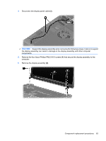
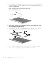
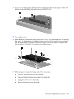
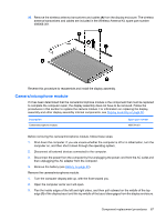
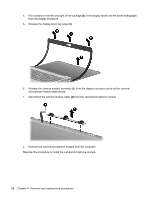
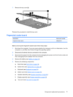
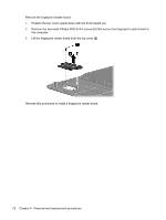
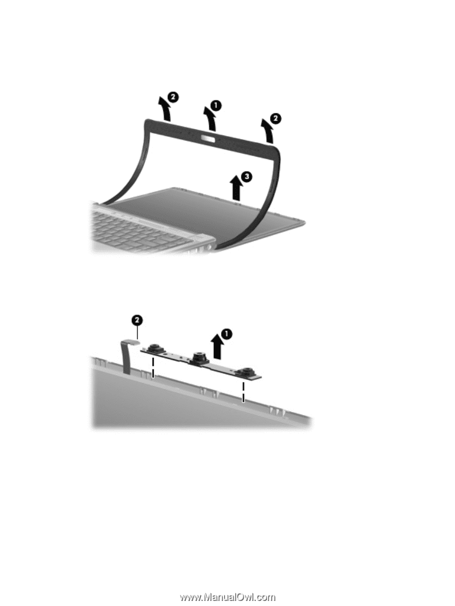
4. Pull outward on the left and right of the top edge (2) of the display bezel until the bezel disengages from the display enclosure. 5. Release the display bezel top edge (3). 6. Release the camera module assembly (1) from the display enclosure as far as the camera/ microphone module cable allows. 7. Disconnect the camera module cable (2) from the camera/microphone module. 8. Remove the camera/microphone module from the computer. Reverse this procedure to install the camera/microphone module. 68 Chapter 4 Removal and replacement procedures
-
 1
1 -
2
-
3
-
4
-
5
-
6
-
7
-
8
-
9
-
10
-
11
-
12
-
13
-
14
-
15
-
16
-
17
-
18
-
19
-
20
-
21
-
22
-
23
-
24
-
25
-
26
-
27
-
28
-
29
-
30
-
31
-
32
-
33
-
34
-
35
-
36
-
37
-
38
-
39
-
40
-
41
-
42
-
43
-
44
-
45
-
46
-
47
-
48
-
49
-
50
-
51
-
52
-
53
-
54
-
55
-
56
-
57
-
58
-
59
-
60
-
61
-
62
-
63
-
64
-
65
-
66
-
67
-
68
-
69
-
70
-
 71
71 -
 72
72 -
 73
73 -
 74
74 -
 75
75 -
 76
76 -
 77
77 -
 78
78 -
 79
79 -
 80
80 -
 81
81 -
82
-
83
-
84
-
85
-
86
-
87
-
88
-
89
-
90
-
91
-
92
-
93
-
94
-
95
-
96
-
97
-
98
-
99
-
100
-
101
-
102
-
103
-
104
-
105
-
106
-
107
-
108
-
109
-
110
-
111
-
112
-
113
-
114
-
115
-
116
-
117
-
118
-
119
-
120
-
121
-
122
-
123
-
124
-
125
-
126
-
127
-
128
-
129
-
130
-
131
-
132
-
133
-
134
-
135
-
136
-
137
-
138
-
139
-
140
-
141
-
142
-
143
-
144
-
145
-
146
-
147
-
148
-
149
-
150
-
151
-
152
-
153
-
154
-
155
-
156
-
157
-
158
-
159
-
160
-
161
 |
 |
4.
Pull outward on the left and right of the top edge
(2)
of the display bezel until the bezel disengages
from the display enclosure.
5.
Release the display bezel top edge
(3)
.
6.
Release the camera module assembly
(1)
from the display enclosure as far as the camera/
microphone module cable allows.
7.
Disconnect the camera module cable
(2)
from the camera/microphone module.
8.
Remove the camera/microphone module from the computer.
Reverse this procedure to install the camera/microphone module.
68
Chapter 4
Removal and replacement procedures