HP Presario CQ45-300 Compaq Presario CQ45 Notebook PC - Maintenance and Servic - Page 87
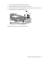
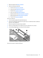
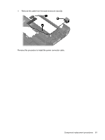
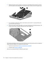
Remove the Phillips PM2.5×4.0 screw, Remove the cable from the base enclosure clips
 |
View all HP Presario CQ45-300 manuals
Add to My Manuals
Save this manual to your list of manuals |
Page 87 highlights
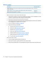
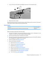
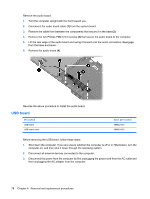
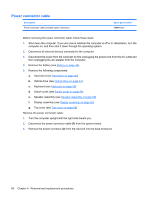
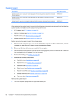
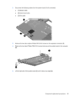
4. Remove the battery (see Battery on page 43). 5. Remove the following components: a. Hard drive (see Hard drive on page 46) b. Optical drive (see Optical drive on page 44) c. Keyboard (see Keyboard on page 56) d. Switch cover (see Switch cover on page 58) e. Speaker assembly (see Speaker assembly on page 60) f. Display assembly (see Display assembly on page 62) g. Top cover (see Top cover on page 69) Remove the USB board: 1. Turn the computer upright with the right side toward you. 2. Disconnect the USB board cable (1) from the system board. The USB board cable is available as spare part number 486842-001. 3. Remove the cable from the base enclosure clips (2). 4. Remove the Phillips PM2.5×4.0 screw (3) that secures the USB board to the computer. 5. Lift the USB board (4) straight up to remove it from the computer. Reverse this procedure to install the USB board. Component replacement procedures 79
-
 1
1 -
2
-
3
-
4
-
5
-
6
-
7
-
8
-
9
-
10
-
11
-
12
-
13
-
14
-
15
-
16
-
17
-
18
-
19
-
20
-
21
-
22
-
23
-
24
-
25
-
26
-
27
-
28
-
29
-
30
-
31
-
32
-
33
-
34
-
35
-
36
-
37
-
38
-
39
-
40
-
41
-
42
-
43
-
44
-
45
-
46
-
47
-
48
-
49
-
50
-
51
-
52
-
53
-
54
-
55
-
56
-
57
-
58
-
59
-
60
-
61
-
62
-
63
-
64
-
65
-
66
-
67
-
68
-
69
-
70
-
71
-
72
-
73
-
74
-
75
-
76
-
77
-
78
-
79
-
80
-
81
-
 82
82 -
 83
83 -
 84
84 -
 85
85 -
 86
86 -
 87
87 -
 88
88 -
 89
89 -
 90
90 -
 91
91 -
 92
92 -
93
-
94
-
95
-
96
-
97
-
98
-
99
-
100
-
101
-
102
-
103
-
104
-
105
-
106
-
107
-
108
-
109
-
110
-
111
-
112
-
113
-
114
-
115
-
116
-
117
-
118
-
119
-
120
-
121
-
122
-
123
-
124
-
125
-
126
-
127
-
128
-
129
-
130
-
131
-
132
-
133
-
134
-
135
-
136
-
137
-
138
-
139
-
140
-
141
-
142
-
143
-
144
-
145
-
146
-
147
-
148
-
149
-
150
-
151
-
152
-
153
-
154
-
155
-
156
-
157
-
158
-
159
-
160
-
161
 |
 |