HP Presario CQ45-300 Compaq Presario CQ45 Notebook PC - Maintenance and Servic - Page 91
Lift the right side of the system board, until it rests at an angle
 |
View all HP Presario CQ45-300 manuals
Add to My Manuals
Save this manual to your list of manuals |
Page 91 highlights
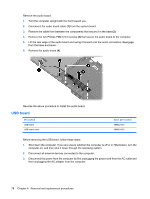
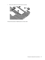
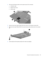
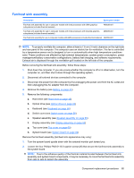
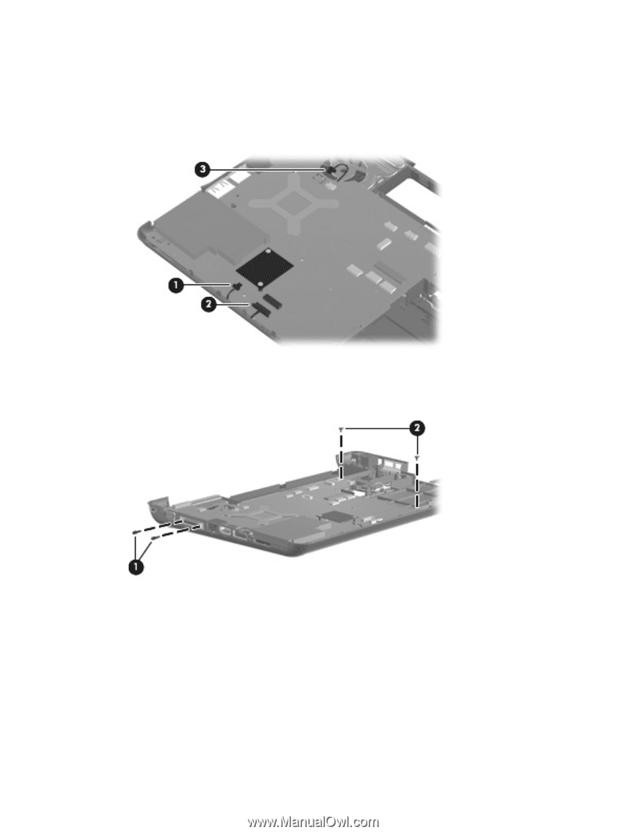
2. Disconnect the following cables from the system board (if still connected): ● (1) Modem cable ● (2) Audio board cable ● (3) Fan cable 3. Remove the two silver captive Phillips PM1.5×9.0 screws on the expansion connector (1). 4. Remove the two black Phillips PM2.5×6.0 screws that secure the system board to the computer (2). 5. Lift the right side of the system board (1) until it rests at an angle (2). Component replacement procedures 83
-
 1
1 -
2
-
3
-
4
-
5
-
6
-
7
-
8
-
9
-
10
-
11
-
12
-
13
-
14
-
15
-
16
-
17
-
18
-
19
-
20
-
21
-
22
-
23
-
24
-
25
-
26
-
27
-
28
-
29
-
30
-
31
-
32
-
33
-
34
-
35
-
36
-
37
-
38
-
39
-
40
-
41
-
42
-
43
-
44
-
45
-
46
-
47
-
48
-
49
-
50
-
51
-
52
-
53
-
54
-
55
-
56
-
57
-
58
-
59
-
60
-
61
-
62
-
63
-
64
-
65
-
66
-
67
-
68
-
69
-
70
-
71
-
72
-
73
-
74
-
75
-
76
-
77
-
78
-
79
-
80
-
81
-
82
-
83
-
84
-
85
-
 86
86 -
 87
87 -
 88
88 -
 89
89 -
 90
90 -
 91
91 -
 92
92 -
 93
93 -
 94
94 -
 95
95 -
 96
96 -
97
-
98
-
99
-
100
-
101
-
102
-
103
-
104
-
105
-
106
-
107
-
108
-
109
-
110
-
111
-
112
-
113
-
114
-
115
-
116
-
117
-
118
-
119
-
120
-
121
-
122
-
123
-
124
-
125
-
126
-
127
-
128
-
129
-
130
-
131
-
132
-
133
-
134
-
135
-
136
-
137
-
138
-
139
-
140
-
141
-
142
-
143
-
144
-
145
-
146
-
147
-
148
-
149
-
150
-
151
-
152
-
153
-
154
-
155
-
156
-
157
-
158
-
159
-
160
-
161
 |
 |
2.
Disconnect the following cables from the system board (if still connected):
●
(1)
Modem cable
●
(2)
Audio board cable
●
(3)
Fan cable
3.
Remove the two silver captive Phillips PM1.5×9.0 screws on the expansion connector
(1)
.
4.
Remove the two black Phillips PM2.5×6.0 screws that secure the system board to the computer
(2)
.
5.
Lift the right side of the system board
(1)
until it rests at an angle
(2)
.
Component replacement procedures
83