HP ProBook 4420s HP ProBook 4320s, 4321s, 4420s, and 4421s Notebook PCs - Mai - Page 102
USB connector board, When replacing the system board
 |
View all HP ProBook 4420s manuals
Add to My Manuals
Save this manual to your list of manuals |
Page 102 highlights
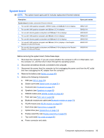
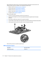
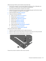
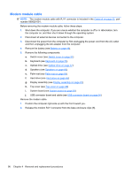
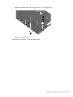
When replacing the system board, be sure that the following components are removed from the defective system board and installed on the replacement system board: ● Memory module (see Memory module on page 55) ● WLAN module (see WLAN module on page 69) ● WWAN module (see WWAN module on page 62) ● Modem module (see Modem module on page 91) ● Processor (see Processor on page 78) Remove the system board: 1. Position the computer right-side up with the front toward you. 2. Remove the T8 slotted-Torx 2.5×5.0 screw (1) that secures the system board to the base enclosure. 3. Disconnect the USB board cable from the system board (2). 4. Use the ODD connector (3) to lift the right side of the system board from the base enclosure (4). 5. Lift the system board up and to the right to remove the system board (5). Reverse this procedure to install the system board. USB connector board Description USB board with cable Spare part number 599524-001 94 Chapter 4 Removal and replacement procedures
-
 1
1 -
2
-
3
-
4
-
5
-
6
-
7
-
8
-
9
-
10
-
11
-
12
-
13
-
14
-
15
-
16
-
17
-
18
-
19
-
20
-
21
-
22
-
23
-
24
-
25
-
26
-
27
-
28
-
29
-
30
-
31
-
32
-
33
-
34
-
35
-
36
-
37
-
38
-
39
-
40
-
41
-
42
-
43
-
44
-
45
-
46
-
47
-
48
-
49
-
50
-
51
-
52
-
53
-
54
-
55
-
56
-
57
-
58
-
59
-
60
-
61
-
62
-
63
-
64
-
65
-
66
-
67
-
68
-
69
-
70
-
71
-
72
-
73
-
74
-
75
-
76
-
77
-
78
-
79
-
80
-
81
-
82
-
83
-
84
-
85
-
86
-
87
-
88
-
89
-
90
-
91
-
92
-
93
-
94
-
95
-
96
-
 97
97 -
 98
98 -
 99
99 -
 100
100 -
 101
101 -
 102
102 -
 103
103 -
 104
104 -
 105
105 -
 106
106 -
 107
107 -
108
-
109
-
110
-
111
-
112
-
113
-
114
-
115
-
116
-
117
-
118
-
119
-
120
-
121
-
122
-
123
-
124
-
125
-
126
-
127
-
128
-
129
-
130
-
131
-
132
-
133
-
134
-
135
-
136
-
137
-
138
-
139
-
140
-
141
-
142
-
143
-
144
-
145
-
146
-
147
-
148
-
149
-
150
-
151
-
152
-
153
-
154
-
155
-
156
-
157
-
158
-
159
-
160
-
161
-
162
 |
 |
