HP ProBook 4420s HP ProBook 4320s, 4321s, 4420s, and 4421s Notebook PCs - Mai - Page 56
Component replacement procedures, Serial number label, Computer feet
 |
View all HP ProBook 4420s manuals
Add to My Manuals
Save this manual to your list of manuals |
Page 56 highlights
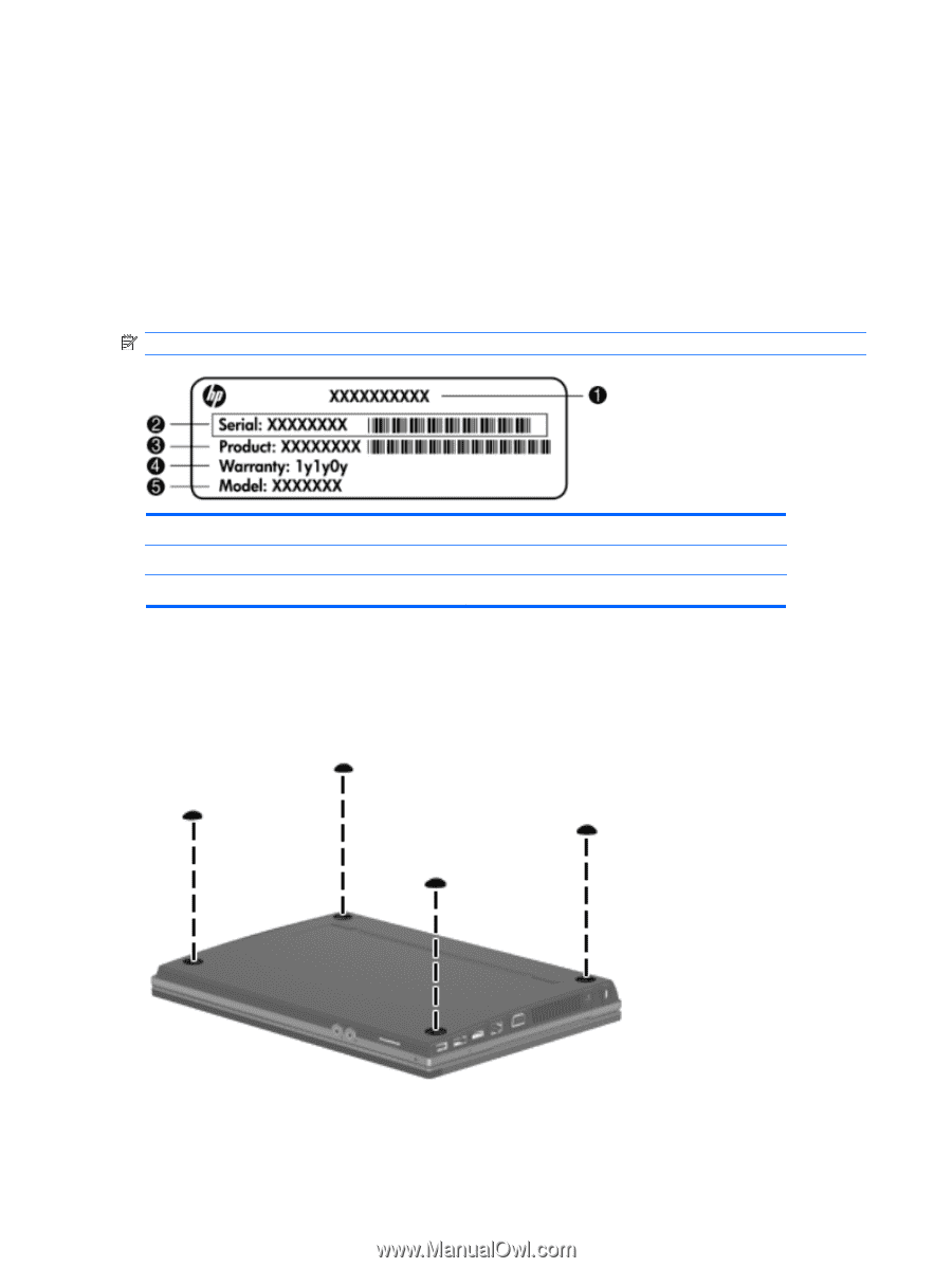
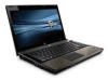
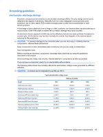
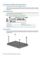
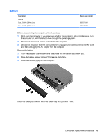
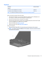
Component replacement procedures This section provides removal and replacement procedures. There are as many as 83 screws, in 8 different sizes, that must be removed, replaced, or loosened when servicing the computer. Make special note of each screw size and location during removal and replacement. Serial number label The serial number label, located on the bottom of the computer, provides important information that you may need when contacting technical support. NOTE: Serial number label color varies on select models. (1) Product name (2) Serial number (3) Product number (4) Warranty period (5) Model description (select models) Computer feet The computer feet are adhesive-backed rubber pads. The feet are included in the rubber kit, spare part number 535793-001. There are 4 rubber feet that attach to the base enclosure in the locations illustrated below. 48 Chapter 4 Removal and replacement procedures
-
 1
1 -
2
-
3
-
4
-
5
-
6
-
7
-
8
-
9
-
10
-
11
-
12
-
13
-
14
-
15
-
16
-
17
-
18
-
19
-
20
-
21
-
22
-
23
-
24
-
25
-
26
-
27
-
28
-
29
-
30
-
31
-
32
-
33
-
34
-
35
-
36
-
37
-
38
-
39
-
40
-
41
-
42
-
43
-
44
-
45
-
46
-
47
-
48
-
49
-
50
-
 51
51 -
 52
52 -
 53
53 -
 54
54 -
 55
55 -
 56
56 -
 57
57 -
 58
58 -
 59
59 -
 60
60 -
 61
61 -
62
-
63
-
64
-
65
-
66
-
67
-
68
-
69
-
70
-
71
-
72
-
73
-
74
-
75
-
76
-
77
-
78
-
79
-
80
-
81
-
82
-
83
-
84
-
85
-
86
-
87
-
88
-
89
-
90
-
91
-
92
-
93
-
94
-
95
-
96
-
97
-
98
-
99
-
100
-
101
-
102
-
103
-
104
-
105
-
106
-
107
-
108
-
109
-
110
-
111
-
112
-
113
-
114
-
115
-
116
-
117
-
118
-
119
-
120
-
121
-
122
-
123
-
124
-
125
-
126
-
127
-
128
-
129
-
130
-
131
-
132
-
133
-
134
-
135
-
136
-
137
-
138
-
139
-
140
-
141
-
142
-
143
-
144
-
145
-
146
-
147
-
148
-
149
-
150
-
151
-
152
-
153
-
154
-
155
-
156
-
157
-
158
-
159
-
160
-
161
-
162
 |
 |