HP ProBook 4535s HP ProBook 4535s Notebook PC - Maintenance and Service Guide - Page 65
Some units have double-sided tape securing the keyboard to the top cover.
 |
View all HP ProBook 4535s manuals
Add to My Manuals
Save this manual to your list of manuals |
Page 65 highlights
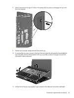
4. Insert a screwdriver or similar tool into the gap near the WWAN module compartment and push to disengage the keyboard. 5. Position the computer upright with the front toward you. 6. Open the computer as far as possible. 7. Lift and rotate the keyboard (1) until it rests on the palm rest (2). NOTE: Some units have double-sided tape securing the keyboard to the top cover. 8. Lift the keyboard connector latch (1). 9. Disconnect the keyboard cable from the system board (2) Component replacement procedures 57
-
 1
1 -
2
-
3
-
4
-
5
-
6
-
7
-
8
-
9
-
10
-
11
-
12
-
13
-
14
-
15
-
16
-
17
-
18
-
19
-
20
-
21
-
22
-
23
-
24
-
25
-
26
-
27
-
28
-
29
-
30
-
31
-
32
-
33
-
34
-
35
-
36
-
37
-
38
-
39
-
40
-
41
-
42
-
43
-
44
-
45
-
46
-
47
-
48
-
49
-
50
-
51
-
52
-
53
-
54
-
55
-
56
-
57
-
58
-
59
-
 60
60 -
 61
61 -
 62
62 -
 63
63 -
 64
64 -
 65
65 -
 66
66 -
 67
67 -
 68
68 -
 69
69 -
 70
70 -
71
-
72
-
73
-
74
-
75
-
76
-
77
-
78
-
79
-
80
-
81
-
82
-
83
-
84
-
85
-
86
-
87
-
88
-
89
-
90
-
91
-
92
-
93
-
94
-
95
-
96
-
97
-
98
-
99
-
100
-
101
-
102
-
103
-
104
-
105
-
106
-
107
-
108
-
109
-
110
-
111
-
112
-
113
-
114
-
115
-
116
-
117
-
118
-
119
-
120
-
121
-
122
-
123
-
124
-
125
-
126
-
127
-
128
-
129
-
130
-
131
-
132
-
133
-
134
-
135
-
136
 |
 |
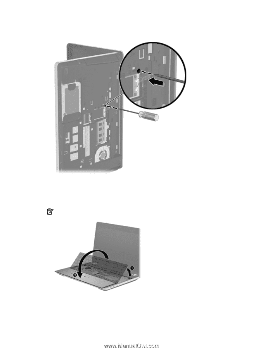
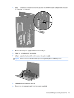
4.
Insert a screwdriver or similar tool into the gap near the WWAN module compartment and push
to disengage the keyboard.
5.
Position the computer upright with the front toward you.
6.
Open the computer as far as possible.
7.
Lift and rotate the keyboard
(1)
until it rests on the palm rest
(2)
.
NOTE:
Some units have double-sided tape securing the keyboard to the top cover.
8.
Lift the keyboard connector latch
(1)
.
9.
Disconnect the keyboard cable from the system board
(2)
Component replacement procedures
57