HP ProBook 4535s HP ProBook 4535s Notebook PC - Maintenance and Service Guide - Page 83
System board, and then unplugging the AC adapter from the computer.
 |
View all HP ProBook 4535s manuals
Add to My Manuals
Save this manual to your list of manuals |
Page 83 highlights
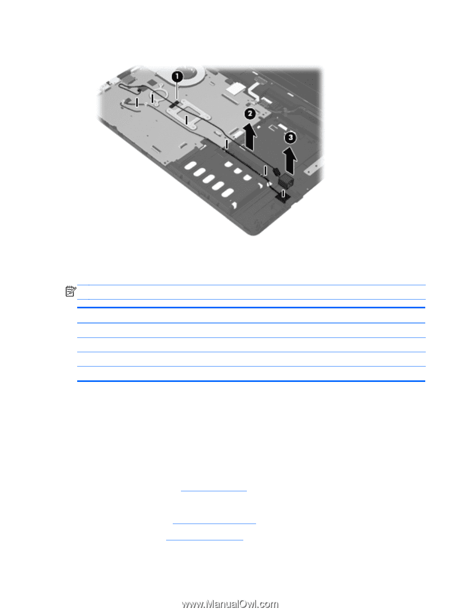
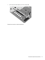
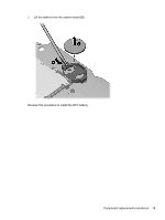
4. Remove the RJ-11 jack from the clip built into the base enclosure (3). Reverse this procedure to install the RJ-11 jack cable. System board NOTE: All system board spare part kits include replacement thermal material. Description System board for use in models with 1-GB of discrete memory System board for use in models with 512-MB of discrete memory System board for use in models with UMA graphics with WWAN System board for use in models with UMA graphics without WWAN Spare part number 654306-001 654307-001 654309-001 654308-001 Before removing the system board, follow these steps: 1. Shut down the computer. If you are unsure whether the computer is off or in Hibernation, turn the computer on, and then shut it down through the operating system. 2. Disconnect all external devices connected to the computer. 3. Disconnect the power from the computer by first unplugging the power cord from the AC outlet, and then unplugging the AC adapter from the computer. 4. Remove the battery (see Battery on page 40). 5. Remove the following components: a. Bottom door (see Bottom door on page 42). b. Hard drive (see Hard drive on page 45) Component replacement procedures 75
-
 1
1 -
2
-
3
-
4
-
5
-
6
-
7
-
8
-
9
-
10
-
11
-
12
-
13
-
14
-
15
-
16
-
17
-
18
-
19
-
20
-
21
-
22
-
23
-
24
-
25
-
26
-
27
-
28
-
29
-
30
-
31
-
32
-
33
-
34
-
35
-
36
-
37
-
38
-
39
-
40
-
41
-
42
-
43
-
44
-
45
-
46
-
47
-
48
-
49
-
50
-
51
-
52
-
53
-
54
-
55
-
56
-
57
-
58
-
59
-
60
-
61
-
62
-
63
-
64
-
65
-
66
-
67
-
68
-
69
-
70
-
71
-
72
-
73
-
74
-
75
-
76
-
77
-
 78
78 -
 79
79 -
 80
80 -
 81
81 -
 82
82 -
 83
83 -
 84
84 -
 85
85 -
 86
86 -
 87
87 -
 88
88 -
89
-
90
-
91
-
92
-
93
-
94
-
95
-
96
-
97
-
98
-
99
-
100
-
101
-
102
-
103
-
104
-
105
-
106
-
107
-
108
-
109
-
110
-
111
-
112
-
113
-
114
-
115
-
116
-
117
-
118
-
119
-
120
-
121
-
122
-
123
-
124
-
125
-
126
-
127
-
128
-
129
-
130
-
131
-
132
-
133
-
134
-
135
-
136
 |
 |