HP ProBook 4535s HP ProBook 4535s Notebook PC - Maintenance and Service Guide - Page 84
Disconnect the webcam cable, Remove the system board
 |
View all HP ProBook 4535s manuals
Add to My Manuals
Save this manual to your list of manuals |
Page 84 highlights
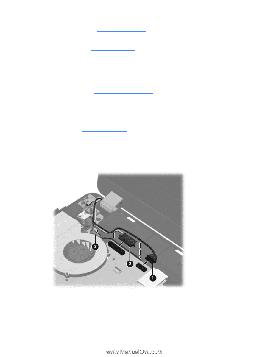
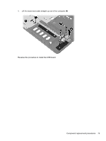
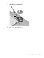
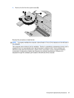
c. Optical drive (see Optical drive on page 43) d. Modem module (see Modem module on page 69) e. Keyboard (see Keyboard on page 56) f. Top cover (see Top cover on page 58) When replacing the system board, be sure to remove the following components from the defective system board and install on the replacement system board: ● SIM (see SIM on page 41) ● Memory module (see Memory modules on page 47) ● WLAN module (see WLAN/Bluetooth combo card on page 51) ● WWAN module (see WWAN module on page 49) ● Modem module (see Modem module on page 69) ● Processor (see Processor on page 84) Remove the system board: 1. Position the computer upright with the front toward you. 2. Disconnect the webcam cable (1) and the display cable (2) from the system board, and remove the cables from the routing clip (3). 3. Remove the Phillips PM2.5×5.0 screw (1) that secures the system board to the base enclosure. 4. Lift the optical drive connector latch (2), and then disconnect the optical drive cable (3). 76 Chapter 4 Removal and replacement procedures
-
 1
1 -
2
-
3
-
4
-
5
-
6
-
7
-
8
-
9
-
10
-
11
-
12
-
13
-
14
-
15
-
16
-
17
-
18
-
19
-
20
-
21
-
22
-
23
-
24
-
25
-
26
-
27
-
28
-
29
-
30
-
31
-
32
-
33
-
34
-
35
-
36
-
37
-
38
-
39
-
40
-
41
-
42
-
43
-
44
-
45
-
46
-
47
-
48
-
49
-
50
-
51
-
52
-
53
-
54
-
55
-
56
-
57
-
58
-
59
-
60
-
61
-
62
-
63
-
64
-
65
-
66
-
67
-
68
-
69
-
70
-
71
-
72
-
73
-
74
-
75
-
76
-
77
-
78
-
 79
79 -
 80
80 -
 81
81 -
 82
82 -
 83
83 -
 84
84 -
 85
85 -
 86
86 -
 87
87 -
 88
88 -
 89
89 -
90
-
91
-
92
-
93
-
94
-
95
-
96
-
97
-
98
-
99
-
100
-
101
-
102
-
103
-
104
-
105
-
106
-
107
-
108
-
109
-
110
-
111
-
112
-
113
-
114
-
115
-
116
-
117
-
118
-
119
-
120
-
121
-
122
-
123
-
124
-
125
-
126
-
127
-
128
-
129
-
130
-
131
-
132
-
133
-
134
-
135
-
136
 |
 |