HP ProBook 4535s HP ProBook 4535s Notebook PC - Maintenance and Service Guide - Page 90
Heat sink - graphics card
 |
View all HP ProBook 4535s manuals
Add to My Manuals
Save this manual to your list of manuals |
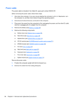
Page 90 highlights
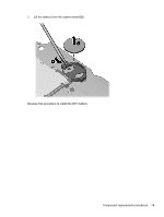
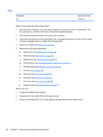
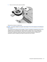
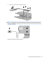
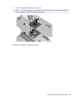
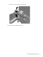
Heat sink All heat sink spare part kits include replacement thermal material. Description Heat sink for use in computers with discrete graphics Heat sink for use in computers with UMA graphics Spare part number 654310-001 654311-001 Before removing the heat sink, follow these steps: 1. Shut down the computer. If you are unsure whether the computer is off or in Hibernation, turn the computer on, and then shut it down through the operating system. 2. Disconnect all external devices connected to the computer. 3. Disconnect the power from the computer by first unplugging the power cord from the AC outlet, and then unplugging the AC adapter from the computer. 4. Remove the battery (see Battery on page 40). 5. Remove the following components: a. Bottom door (see Bottom door on page 42). b. Hard drive (see Hard drive on page 45) c. Optical drive (see Optical drive on page 43) d. WLAN module (see WLAN/Bluetooth combo card on page 51) e. WWAN module (see WWAN module on page 49) f. Fan (see Fan on page 80) g. Heat sink (see Heat sink on page 82) h. Keyboard (see Keyboard on page 56) i. Top cover (see Top cover on page 58) j. System board (see System board on page 75) k. Fan (see Fan on page 80) Remove the heat sink: 1. Position the system board upright. 2. To remove the UMA heat sink, in the order indicated, loosen the four captive Phillips screws (1) - (4) that secure the heat sink to the system board. 82 Chapter 4 Removal and replacement procedures
-
 1
1 -
2
-
3
-
4
-
5
-
6
-
7
-
8
-
9
-
10
-
11
-
12
-
13
-
14
-
15
-
16
-
17
-
18
-
19
-
20
-
21
-
22
-
23
-
24
-
25
-
26
-
27
-
28
-
29
-
30
-
31
-
32
-
33
-
34
-
35
-
36
-
37
-
38
-
39
-
40
-
41
-
42
-
43
-
44
-
45
-
46
-
47
-
48
-
49
-
50
-
51
-
52
-
53
-
54
-
55
-
56
-
57
-
58
-
59
-
60
-
61
-
62
-
63
-
64
-
65
-
66
-
67
-
68
-
69
-
70
-
71
-
72
-
73
-
74
-
75
-
76
-
77
-
78
-
79
-
80
-
81
-
82
-
83
-
84
-
 85
85 -
 86
86 -
 87
87 -
 88
88 -
 89
89 -
 90
90 -
 91
91 -
 92
92 -
 93
93 -
 94
94 -
 95
95 -
96
-
97
-
98
-
99
-
100
-
101
-
102
-
103
-
104
-
105
-
106
-
107
-
108
-
109
-
110
-
111
-
112
-
113
-
114
-
115
-
116
-
117
-
118
-
119
-
120
-
121
-
122
-
123
-
124
-
125
-
126
-
127
-
128
-
129
-
130
-
131
-
132
-
133
-
134
-
135
-
136
 |
 |