HP ProBook 4535s HP ProBook 4535s Notebook PC - Maintenance and Service Guide - Page 97
from the hinges, noting the grounding wire, connected to the screw in the left hinge
 |
View all HP ProBook 4535s manuals
Add to My Manuals
Save this manual to your list of manuals |
Page 97 highlights
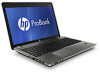
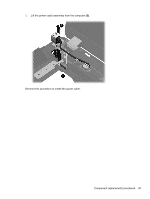
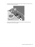
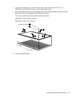
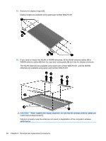
3. If necessary, disconnect the webcam cable (1) and display cable (2) from the system board, and then remove the cables from the clip (3). 4. Remove the four Phillips PM2.5×7.0 screws (1) from the hinges, noting the grounding wire connected to the screw in the left hinge (2). Component replacement procedures 89
-
 1
1 -
2
-
3
-
4
-
5
-
6
-
7
-
8
-
9
-
10
-
11
-
12
-
13
-
14
-
15
-
16
-
17
-
18
-
19
-
20
-
21
-
22
-
23
-
24
-
25
-
26
-
27
-
28
-
29
-
30
-
31
-
32
-
33
-
34
-
35
-
36
-
37
-
38
-
39
-
40
-
41
-
42
-
43
-
44
-
45
-
46
-
47
-
48
-
49
-
50
-
51
-
52
-
53
-
54
-
55
-
56
-
57
-
58
-
59
-
60
-
61
-
62
-
63
-
64
-
65
-
66
-
67
-
68
-
69
-
70
-
71
-
72
-
73
-
74
-
75
-
76
-
77
-
78
-
79
-
80
-
81
-
82
-
83
-
84
-
85
-
86
-
87
-
88
-
89
-
90
-
91
-
 92
92 -
 93
93 -
 94
94 -
 95
95 -
 96
96 -
 97
97 -
 98
98 -
 99
99 -
 100
100 -
 101
101 -
 102
102 -
103
-
104
-
105
-
106
-
107
-
108
-
109
-
110
-
111
-
112
-
113
-
114
-
115
-
116
-
117
-
118
-
119
-
120
-
121
-
122
-
123
-
124
-
125
-
126
-
127
-
128
-
129
-
130
-
131
-
132
-
133
-
134
-
135
-
136
 |
 |
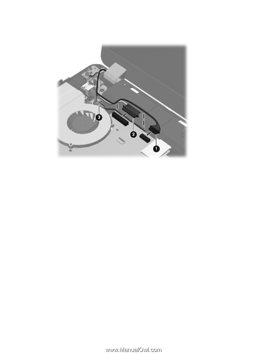
3.
If necessary, disconnect the webcam cable
(1)
and display cable
(2)
from the system board, and
then remove the cables from the clip
(3)
.
4.
Remove the four Phillips PM2.5×7.0 screws
(1)
from the hinges, noting the grounding wire
connected to the screw in the left hinge
(2)
.
Component replacement procedures
89